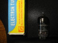
Merry Xmas all.
I thought I would have a play with 6N3P-EV dual triode on the Avo Mk3 tester and graph the results. There seems to be wildly varying curves for these tubes on the net, most showing extreme non-linearity which was not borne out by audible testing. What do you guys think of the linearity?
The Vg figures are RMS values as measured on a scope as the Avo tester uses pseudo-AC (half-wave rectified unfiltered) for its supplies.
P.S. Sorry about the hand sketch graph, I don't have a plotter for this.
Gary
http://i753.photobucket.com/albums/xx178/rotaspec/Amplifiers/6N3P-EV_Avo3_curves.jpg
I only tested a couple 6N3Ps, but they all seemed to bias up the same.
In addition, the distortion (at least with a current source in the anode and IR LED in the Cathode) was low as indicted by low harmonic distortion.
Are you using 6N3P or 6N3P-E tubes?
I am using 6N3P-EV. I have tried the LED bias with good results, but have yet to get around to adding a CCS on the anode side.
I thought I would just try some characteristic measurements with a tester that allows stepping the voltages. I have done the same for 6N1P-EV and 6N2P-EV as well.
Attachments
- Status
- This old topic is closed. If you want to reopen this topic, contact a moderator using the "Report Post" button.
