Greetings all.
I have a question. I have heard / read of an old standard of running the screen voltage at one half of the Plate voltage.
I have seen several driver stages using this but output stages I think only two (Music Reference is the only one I can remember).
I can understand a guitar amp and wanting to keep the screens cooler by running a lower voltage while the plates are very high.
In my situation, I am working through an EL84 PP amp and have a pair of original Dynaco Z565's but want to run Pentode for now.
The tube charts give characteristics at plate and screen voltages as 250 volts or 300 volts. I took a quick look at a few other tubes and they all are similar in that none I saw had specs for a screen at half the plate voltage.
My thoughts are to run the plates at 300 volts and regulate the screens at 150 with a VR150.
So, where does this half b+ for the screens come from ?
Thanks for the help.
So, where does this half b+ for the screens come from ?
Legend.
There's really no reason that one particular screen voltage is the universally correct one. The optimum depends on the tube, the load, the operating point, and the required output power. For your setup, the "book" values would be my starting point, not some audiophile myth.
Pearhaps from the behaviour of old Pure Tetrodes where plate voltage was not allowed to go below the screen one unless you want to build an oscillator or blow the screen.So, where does this half b+ for the screens come from ?
Then came Beam Power Tetrodes and Pentodes . . .
Yves.
"So, where does this half b+ for the screens come from ?"
The TV Sweep tubes sometimes have the "book" values of screen voltage at roughly 1/2 the idle plate voltage. Like 250 V and 150 V (6JN6, 6GE5). The later Sweeps were almost always designed for lower screen voltages than the earlier audio types. The very early pentodes would have lacked the aligned grids to hold screen current down, so would have required reduced screen voltages to avoid screen meltdown. Looking at the "modern" Sweeps on a curve tracer, one will often find that a reduced screen voltage helps alleviate kinks in the curves near the "knees". This "screen current distortion" effect (which sets in when plate V drops below screen V) is usually only relevant to the signal at near clipping levels (for the Sweeps, but can be more problematic with the Audio types since plate V can more easily drop below screen V, but is usually a smaller kink then ). If one does use a lower than normal (book) screen voltage, the g1 negative bias will have to be less too, so less output AC current will be available from the tube. That will require a higher B+ and a higher Zpri OT to get rated power then.
The TV Sweep tubes sometimes have the "book" values of screen voltage at roughly 1/2 the idle plate voltage. Like 250 V and 150 V (6JN6, 6GE5). The later Sweeps were almost always designed for lower screen voltages than the earlier audio types. The very early pentodes would have lacked the aligned grids to hold screen current down, so would have required reduced screen voltages to avoid screen meltdown. Looking at the "modern" Sweeps on a curve tracer, one will often find that a reduced screen voltage helps alleviate kinks in the curves near the "knees". This "screen current distortion" effect (which sets in when plate V drops below screen V) is usually only relevant to the signal at near clipping levels (for the Sweeps, but can be more problematic with the Audio types since plate V can more easily drop below screen V, but is usually a smaller kink then ). If one does use a lower than normal (book) screen voltage, the g1 negative bias will have to be less too, so less output AC current will be available from the tube. That will require a higher B+ and a higher Zpri OT to get rated power then.
Last edited:
Understanding how to use pentodes is such a challange for me. SY said start with "book" values. What book is this?
The data sheet (ref 6BQ5) has plate and screen at the same voltage is this "Book" value. Where I loose it is I haven't seen a schematic that shows Va and Vg2 at the same level. Vg2 is usually 10% to 20% less than Va. I understand this is to help reduce distortion near the clip points. I believe that Guitar amps play with the separation of Va and Vg2 as a means of creating controlled distortion.
The successful use of pentodes seems to be determined by Vg2. Any help or names of books is appreciated.
T
Understanding how to use pentodes is such a challange for me. SY said start with "book" values. What book is this?
I'd use the Mullard datasheets- they are very complete and comprehensive. RCA tube manual also gives much of this information. Generally, the people who made these tubes knew pretty well how they should be run.
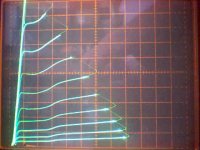
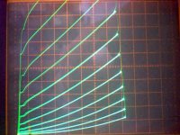
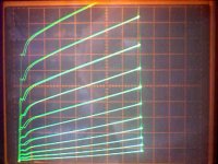
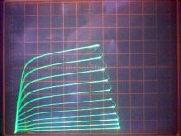
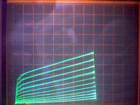
Here are some curve tracer plots for a 38HE7 Sweep pentode, which has noticeable screen current kinking.
Screen voltages at 175 V, 125 V, 75 V, 50 V, and 25 V. The vertical plate current axis scaling gets progressively reduced as well as the grid voltage step size.
Screen voltages at 175 V, 125 V, 75 V, 50 V, and 25 V. The vertical plate current axis scaling gets progressively reduced as well as the grid voltage step size.
Attachments
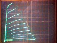
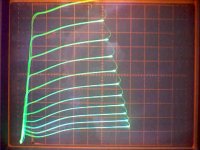
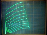
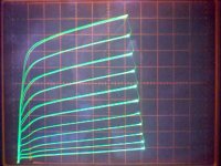
The previous 38HE7 was a typical low screen voltage horizontal Sweep tube.
Here is a high screen V 6JC5 vertical sweep at screen V of 230 V, 135 v, 75 V, and 35 V. Vertical axis plate current scaling progressively reduced as well as g1 V step sizes as before.
edit: and one more at 350 V screen (same screen V overating as the 175 V for the 38HE7)
Here is a high screen V 6JC5 vertical sweep at screen V of 230 V, 135 v, 75 V, and 35 V. Vertical axis plate current scaling progressively reduced as well as g1 V step sizes as before.
edit: and one more at 350 V screen (same screen V overating as the 175 V for the 38HE7)
Attachments
Last edited:
So, where does this half b+ for the screens come from ?
Thanks for the help.
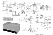
It can come from the middle tap of the power supply transformer, as per the schematic:
Attachments
So, where does this half b+ for the screens come from ?
I have no idea as I've never heard of this, at least not concerning audio. May be an RF practice?
You have a wide variety of different screen voltages and characteristics, depending on the design and likely usage. A lot of audio finals (6V6, 6AQ5, 50C5, 50L6) were designed to operate the plate and screen at the same voltage to either make ultralinear operation possible, and/or to avoid the need for voltage dropping and regulation.
Other types (807-oids, most TVHD finals) were designed to maximize efficiency, and so run the screen at a very low voltage to minimize power loss in the screen circuit where it contributes nothing to power output. These types typically put the screen very close to the cathode, and can't stand high voltage at the screen anyway.
As for screen voltages, try the spec sheets. Even if you don't find any recommended audio bias points, and loads, you still might be able to find a decent audio loadline.
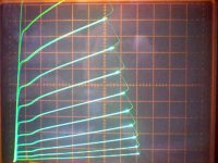
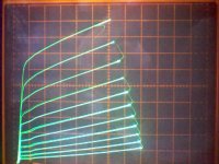
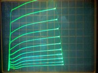
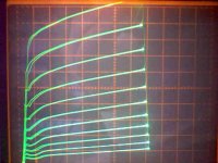
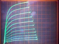
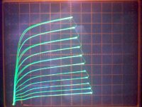
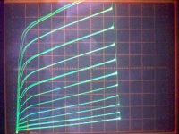
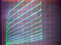
Here are some curve sets for 29GK6 which is essentially the same as 6BQ5.
Screen V at 300 V, 250, 200, 150, 100, 50, and 50 again. Vertical plate current scaling and g1 step V's reducing progressively with lower screen V's.
The last 50 V plot is shown at the same vertical current scale as the 100 V plot. Just to show that the plate resistance Rp may actually be increasing slightly (flatter lines), or the same, with lower V screens, despite the more ramped appearance from the lower vertical scaling on the other graphs.
Attachments
Last edited:
Thanks Guys.
Perhaps there was some sort of "rule" like this in the very early days as suggested by Yves, I can understand that, and of course it would have absolutely no bearing on modern tubes.
Perhaps it also has something to do with the tube tv's and the use of sweep tubes in them. In any case I will stick to the "books".
Smoking Amp, those pics were very thoughtful of you to add and interesting!
I am going to take a look at the 29GK6 at least.
Andrew
I don't know where the half voltage screen statement come from either. Yes some sweep tubes may run with the screen at half the supply, but that may be just coincidence. I have been experimenting with lots of sweep tubes in Petes big red board. The tubes intended for vertical sweep (essentially audio tubes) tend to want the screen near the plate voltage. The tubes intended for horizontal sweep (switched CCS's in normal operation) tend to work best with the screen at or near 150 volts regardless of the plate voltage. Tests were run on little 12 watt tubes all the way up to 40 watt big boys, from 300 volts to 650 volts on the plate. All of them worked the best at 150 volts on G2.
For those who haven't delved deep into tube type TV, there are two sweep circuits.
The vertical sweep circuit moves the CRT's electron beam up and down on the CRT face using electromagnets mounted on the CRT neck (the deflection yoke). The vertical oscillator generates a ramp that must be amplified in a linear manner by the vertical output tube. The vertical output tube functions exactly the same as an audio amp except that it works at only 60 Hz (50 Hz). Early TV's used audio tubes like the 6V6, 6K6, 6W6 and even the 6SN7. Later speciallized tubes incorporating the oscillator and output tube in one envelope were designed. Some use a triode output section, others use a pentode. All of them make good audio amps.
The horizontal sweep circuit moves the beam from side to side, by driving the yoke, and it generates the high voltage (10 to 30 KV) needed for operating the CRT by pulsing the flyback transformer. A clever engineer somewhere made use of the CCS characteristics of a pentode, and the fact that an inductor will charge at a linear rate when fed a constant current, to do both functions in a single circuit. The horizontal oscillator generates a square wave that switches the output tube between cutoff and G1 = 0V. The voltage on G2 sets the current through the output tube. This is why you will find screen curves with G1 = 0V in the data sheets. The tube is switched on and the flyback transformer begins to charge at a linear rate. A winding on the flyback feeds the deflection signal to the yoke. As the current reaches max the beam is moved to the right side of the TV screen. The output tube switches off (like the breaker points in an old car) and the current through the flyback ceases creating a huge voltage spike. The flyback has a HV winding like the ignition coil in your car that feeds a rectifier tube generating the HV. The damper tube squelches (damps) the ringing inherent in a flyback transformer capturing the ringing energy reusing it to create a boosted B+ voltage for other circuits. The current for the horizontal sweep circuit passes through the damper tube, voltages can exceed 500 volts on the cathode, and the plate sees 1KV+ pulses. Yes, these tubes make excellent rectifiers in our amps too.
Horizontal sweep tubes are not designed or intended for linear operation. Some but not all will work in audio applications. The low G2 rating precludes UL operation although a few will work in triode.
Back to the EL84. There are so many tubes out there being called EL84 that it is impossible to characterize them all based on the performance of a few, but I have been experimenting on a Simple P-P board with two power supplies. I find that for every plate voltage there is a screen voltage that produces the lowest THD, and a different voltage that minimizes the higher order harmonics. These voltages vary quite a bit with different versions of EL84. I decided that the JJ EL84 is the best of the reasonably priced current production tubes. At plate voltages around 300 volts the screen wants to be near 300 to get any power output. At plate voltages in the 400 volt range the screen wants to be around 325 volts. 25 watts are possible at THD numbers in the 0.5% range!
Using a screen supply voltage of half the B+ was very common practice amongst guitar amplifier builders here in Australia during the 1970's. The output valve of choice was the 6CA7, and the Philips data sheets gave operating conditions for this configuration.
A voltage doubler power supply was used to produce a B+ of 750-800 volts and the screen supply was taken from the mid-point of the doubler. This configuration worked quite reliably with the Mullard and Philips 6CA7's of that era, but as the quality of valves steadily declined over the years, suitable replacements became problematic.
A voltage doubler power supply was used to produce a B+ of 750-800 volts
and the screen supply was taken from the mid-point of the doubler. This configuration worked quite reliably with the Mullard and Philips 6CA7's of that era, but as the quality of valves steadily declined over the years, suitable replacements became problematic.So George, that means that a distortion analyzer is critical to getting the optimum performance out of pentode outputs. In your experiments was the minimum high order distortion point also the point that minimized HD3 in general? It is somewhat discomforting that different versions of the same tube show such variation.
I'd agree with darry-h and Wieslaw Lipowsk that powering was a major influence - there are a variety of power rectifier configurations that naturally generate a 50% HT rail. KT88's enjoyed a 50% screen as well for higher powered PP amps. Wieslaw's rectifier example was also used by Philips in their PA commercial amps - eg. with EL36/PL36/6CM5.
Ciao, Tim
Ciao, Tim
Here's an interesting production vintage amp with a really high plate V. and half the screen. Looks like a regular mono amp and not PA? Has a separate PS trans winding for screen V. What's the reason on this one and will the Output tubes last longer?
Randy
Randy
Attachments
Last edited:
Imho the amp can be modded somewhat to reduce distortion related affects - it's then up to your golden ears. Half voltage screen does not per se relegate an amp as far as distortion.
The first thing would be to measure the turns ratio's of all the secondary segments, and see what opportunity exists for reconfiguring winding segments - with the aim of using as much of the secondary copper as possible for a speaker matched output.
Ciao, Tim
The first thing would be to measure the turns ratio's of all the secondary segments, and see what opportunity exists for reconfiguring winding segments - with the aim of using as much of the secondary copper as possible for a speaker matched output.
Ciao, Tim
- Status
- This old topic is closed. If you want to reopen this topic, contact a moderator using the "Report Post" button.
- Home
- Amplifiers
- Tubes / Valves
- Output Pentode Screen at half Plate voltage