What difference does it make? In either case the OPT hardly gets hot until you have seriously over driven it.
However, for power transformers power is rated in RMS watts due to heating and longevity issues. For audio signal power is usually provided in peak power, not rms. To wit, a typical amplifier cannot exceed 48% of it's DC plate voltage in peak to peak swing voltage. To know what you need to allow for in terms of core saturation voltage you multiply that peak voltage by the usual 0.707 for rms ac drive voltage.
But again, very few amplifiers ever work near their peak power and very few OPT's ever get warm from that power being used. If the catalog says 10 watts I am sure you can draw that much from the thing. Just check to see what the expected load is, so you know how much ac swing voltage is going to be needed to provide the power. Then figure out the turns required to make that impedance and check to see if the flux is going to saturate the core.
Or, call them and ask. They will tell you. It is in their best interests for you to use their products for the goals they chose, when designing them.
Bud
No such thing as RMS power. RMS is voltage or current.
For a sine wave AC circuit: Vrms= sqrt( Pavg x R)
Transformer power, whether audio or mains, should be average watts. For audio this will be the average continuous power, given certain conditions. For mains this will be power into a resistive load. You will get less power into a rectifier, as the peaky nature of the secondary current means more copper heating.
All transformer design values are based upon RMS voltage and current loading. All of them are based upon heating, from full power developed from full loads for a 100% duty cycle, unless the duty cycle derating has a specified time interval and a guarantee of that activity being enforced in a fail proof manner.
Average power draw is meaningless in both audio and mains connections.
Average power draw is meaningless in both audio and mains connections.
I wasn't concerned about overloading the OPT. I assumed a SE 6BQ5 wouldn't challange a 10 Watt OPT. I was trying to determine the correct values to use in the design process when calculating max output.
For a Newbie (Me) to better understand what you said,
Is it: 250 (DC Plate) X .48= 120 P-P X .707 = 85V RMS
Or is it: 250 (DC Plate) X .48 = 120 X 2 = 240 P-P X .707 = 170V RMS
Again I'm going to assume for max you would use highest voltage on the load line, which would be more like 330V (DC Plate)
Which would be 224V RMS
By the way thanks a lot for your previous posts on this thread.
T
Last edited:
Both of your formulas are correct. The 85 vac rms is the swing voltage for 1/2 of the primary which is what you utilize when calculating flux density in the typical manner.The full primary is what is enlisted to describe the load line or turns ratio and the eventual voltage swing in the secondary from a full polarity swing in the primary.
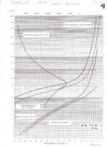
You can use either idle plate voltage or max load line voltage. However, the load line maximum of ~112 vac rms might saturate a poorly designed OPT. I have attached a permeability curve for AC rms flux density vs perm. This is the one you would use in calculating the inductance of a SE OPT with a DC bias and gap or a power core for a choke. Peak perm is quite a bit higher, is useful only for nonsinusoidal pulse calculation. I have attached a perm curve for M6 (Hi B) core out of eastern Europe somewhere. Look at the Amplitude Permeability curve and the upper mu measures. Then note the increase towards 20 Hz and know that that increase in % from 50 Hz to 20 Hz will be available at 20 Hz from the permeability curves for AC RMS, which are also based upon 50/60 Hz.
Also note that it makes no sense to be more precise than this because core nominals range from + to - 25%, from a basically unstated mean. The M series perms shown are what I expect as minimum permeability and you can generally expect a 25% gain over them. The starting point of each line is for 1 volt 100/120 Hz excitation and is useful for calibrating the core you intend to use and for extrapolating the performance of an unknown transformer.
Attachments
Last edited:
Thank you for the in depth info on OPT permeability. I do know it is the nature of the beast and adversely effects performance. It will take me a while to understand the exact effect it has on power output and performance.
When dealing with typical off the shelf DIY opt's we tend to rely on reviews of others and what ever testing we are capable of. It would be useful for comparison if the common (Hammond, Edcor, James, Etc) OPT manufactures would provide this info.
However your info may help clear up one confusing issue I have when studding the designs of others. Is the permeability effects why some designs use 15 Watt OPTs when their power tube is only capable of about 5 watts?
I do understand that bigger is better, to a point.
Thanks Again for all your great input.
T
When a manufacture specifies 10W. Is that Peak or RMS. Like the Edcor GXSE10-8-5K. It just says 10 Watt.
Peak or RMS, it is a worthless spec when there is no specification of power bandwidth.
About every OPT will show core saturation at some low frequency, important is where that point is. So 10W at 20Hz says a lot more.
Here are the basic formulas for manipulating and analyzing transformer core performance characteristics. Use the data from the perm chart where applicable.
1.) input voltage X 10 to the fifth /4.44 X core area of flux tube X frequency X primary turns X stacking factor (usually 92% for E/I core) will provide you with the flux density in kilolines per square inch for an AC rms input.
2.) 3.49 X input voltage X 10 to the sixth/ frequency X core area of flux tube X stacking factor (usually 92% for E/I core) X primary turns will provide you with the flux density in kilogauss per square centimeter for an AC rms input.
Multiply 1.) by 0.155 to obtain flux in kilogauss. 1.) and 2.) will provide slightly different values, ignore this.
3.) 0.6 X total primary turns X DC current flowing in the primary / total gap thickness (all of the gaps added together for one magnetic path) will provide you with the flux density for a DC current flowing in the primary of a gaped SE OPT.
4.) 3.2 X primary turns squared (full primary) X core area of flux tube X permeability / core magnetic path length X 10 to the 8th will provide the ac rms permeability of the transformer in question.
For gaped core you replace the permeability with the following complex addition. 1/permeability + total gap thickness (all of the gaps added together for one magnetic path) / magnetic path length. You can obtain the magnetic path length from the Thomas and Skinner lamination catalog found here Thomas and Skinner - Transformer Laminations
Obviously there are other derivations for the above formulas. If you use the inductance found at minimum excitation and manipulate the third formula, you can arrive at a pretty close approximation of the primary turns used in the coil. This will allow you to take a look at the flux density for SE OPT's and PP OPT's or power transformers.
The reason people use larger transformers than what is specified is that they do not have access to the above formulas and perm charts. They got badly burned once or like belts and suspenders and in either case the information needed was just not available, so they figured X three ought to just about do it.
Size does matter and to a point bigger is actually better, for some designers work. Not so for others.
Bud
Last edited:
4.) 3.2 X primary turns squared (full primary) X core area of flux tube X permeability / core magnetic path length X 10 to the 8th will provide the ac rms permeability of the transformer in question.
Should be altered to this.
4.) 3.2 X primary turns squared (full primary) X core area of flux tube X 92% stacking factor X permeability / core magnetic path length X 10 to the 8th will provide the ac rms inductance of the transformer in question.
Bud
- Status
- This old topic is closed. If you want to reopen this topic, contact a moderator using the "Report Post" button.
- Home
- Amplifiers
- Tubes / Valves
- OPT Question