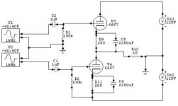
Ive breadboarded a simple Inverted Futterman OTL based on the Ciuffoli 'cheap and cheerful' design.
I noticed in the original design the neg/lower valve was apparently autobias, so Ive done the same with the top tube too....(100 ohm decoupled by 2200uF both tubes)
Its supply is only around 100V plus/minus for the O/P stage and I'm using 6C33 biassed at 175mA. so there'll be much lower power than the original.
--I dont need huge power, at a guess, Its making around 10-15W, not checked yet...
Its been run for a few days on all sorts of music and different sources. Ive made a few changes to the original design like the coupling-caps to the O/P pair are now 0.22 instead of 22uF and the grid-resistors are now 180K instead of 68K. (originals caused pumping/blocking)
A few more simple alterations, and I must say it sounds really quite good.
Any thoughts...?")
I noticed in the original design the neg/lower valve was apparently autobias, so Ive done the same with the top tube too....(100 ohm decoupled by 2200uF both tubes)
Its supply is only around 100V plus/minus for the O/P stage and I'm using 6C33 biassed at 175mA. so there'll be much lower power than the original.
--I dont need huge power, at a guess, Its making around 10-15W, not checked yet...
Its been run for a few days on all sorts of music and different sources. Ive made a few changes to the original design like the coupling-caps to the O/P pair are now 0.22 instead of 22uF and the grid-resistors are now 180K instead of 68K. (originals caused pumping/blocking)
A few more simple alterations, and I must say it sounds really quite good.
Any thoughts...?
Can you post a circuit, please?
Andy
.
Hi Andy,
Andria's Schematic that I based this on is here-
http://www.audiodesignguide.com/my/OTL_version_82_cheap.gif
The only fundamental change was the addition of the extra resistor and decoup cap in the top valve's cathode. The Speaker is connected at the anode of the lower valve, not at the cathode of the upper.
Ive changed a few values and tubes. I'm using 6SN7 for first and second stages and a 6J5G for the phase-split. The coupling-caps to O/P pair are now 0.22uF instead of the 22uF of Andria's design, and their associated grid-resistors are 180K instead of 68K (following the 6C33C guidance in the valve's spec. sheet, max recommended is 220K)
--I originally had 10uF here in the grid-drive, from P/S but found that under high O/P I was getting 'blocking/pumping' of the speaker-cone--Funnily enough, Only on one music track....
Offset volts with an 8 ohm load varies between 10mV and 50mV depending on what valves are used in the O/P stage, so I'm happy with that side of things.
Semperfi-
Yes, your scheme is roughly the idea, (For the O/P pair) but the earth return of phase-splitter is returned to the speaker output point at the anode of bottom tube. (Futterman idea)
Guess there are Caps in the signal path, but I was looking to make a Very simple OTL with no worries of bias volts supplies or drift with ageing or different valves/mis-matched valves.
--Worst offset I get with two completely different 'gm' 6C33C valves is around 50mV, so the autobias seems to take care of most issues there...
It sounds very nice to my ear, comparable with my circlotron I made some years ago...
nice idea.
R16 (16R) represents the speaker load?
Best to look at This diagram, its much more like what Ive built--The speaker connections are clearly shown,--no chance of error......
http://www.audiodesignguide.com/my/OTL_version_82_cheap.gif
The above diagram posted by Semperfi doesnt have the right drive format, or the connection of the earthy end of phase-splitter to the speaker output connection--which makes a Futterman, a Futterman....
Yes indeed R12 (16ohm resistor) is the load. In this simulation using only one 6AS7 it is little interest in using a standard 8ohm load.
The 'drive format' is for simulation of the output stage only, although it can be done that way. And it's true I'd never do the Futterman way of doing it;D
The 'drive format' is for simulation of the output stage only, although it can be done that way. And it's true I'd never do the Futterman way of doing it;D
Last edited:
Hello.
My name is Florindo.
I just set up a channel of this amp.
But i am facing some problems.At start up my fuses blows (1A)
All seems to work Ok without the 6c33 valves.Anodic is 160V witout tubes.
When i am inserting the tubes the voltage rise up only until 35V DC and when i switch on the full anodic tension the fuses blows.
Could you maybe provide me a list of the right values of tension in different parts of the circuit.
It could be a help
Thanks in advance
As with all cathode biased amps you will get a high current surge at turn-on if the cathode is warmed up. This b/c the bypass caps are a virtual short untill theyre charged up. Either slow down the heater and have b+ on as they heat up, or have some current limiting at turn-on.
Also, I've come to the habit of oversizing the fuse a tad to give some headroom. And of course use slo-blo fuses.
Also, I've come to the habit of oversizing the fuse a tad to give some headroom. And of course use slo-blo fuses.
Have you let your 6C33C have a burn in period with heater only no B+
If you turn it on brand new you can be unlucky and have a short in the tube.
The 6c33c starts perfoming well after a week of use sounding very boring and flat in the beginning.
If you turn it on brand new you can be unlucky and have a short in the tube.
The 6c33c starts perfoming well after a week of use sounding very boring and flat in the beginning.
Hello.
My name is Florindo.
I just set up a channel of this amp.
But i am facing some problems.At start up my fuses blows (1A)
All seems to work Ok without the 6c33 valves.Anodic is 160V witout tubes.
When i am inserting the tubes the voltage rise up only until 35V DC and when i switch on the full anodic tension the fuses blows.
Could you maybe provide me a list of the right values of tension in different parts of the circuit.
It could be a help
Thanks in advance
Thanks gys fir this hint.
But explain the following: With tubes inserted and the +B inserted with the resistor 10K mounted after the bridge the voltage rises up only to 35V (Heathers on) even after a wile the tension remains the same.
When i by pass the resistor and opensthe full voltage the fuse blows
But explain the following: With tubes inserted and the +B inserted with the resistor 10K mounted after the bridge the voltage rises up only to 35V (Heathers on) even after a wile the tension remains the same.
When i by pass the resistor and opensthe full voltage the fuse blows
Hi from Flo.
Thanks for your replay.What are you meaning by this: If i have a short in the tube is the tube faulty and not usable anymore?
I made this test (Fuses blown down) with 2 set's of 6c33 always with the same problem
What about the 35V not raising to 150 with tube's inserted but with the 10K resistor inserted??
thanks
If i made some burn in (1 week) would the tube respond better?
Thanks gys fir this hint.
But explain the following: With tubes inserted and the +B inserted with the resistor 10K mounted after the bridge the voltage rises up only to 35V (Heathers on) even after a wile the tension remains the same.
When i by pass the resistor and opensthe full voltage the fuse blows
10K after the bridge?
Do you power up heaters and B+ all togeather no delay on the B+..<<<slow current increase..
OK...if you run the driver stage on its own no 6c33c's in the socket is everything OK?
Then run the 6c33c's on their own..do you get correct bias on the cathode resistors..?
Do you have inrush suppression?
Regards
M. Gregg
Last edited:
Hello Gregg
Yes, without any 6c33 tubes all the voltages are OK and no SHORT CIRCUIT at all (Fuses OK)
Voltages drop to 150V plus and minus in aprox 1/2 minutes.When i inserted the 6c33
I power up heathers with +B together.The voltage rise up until 60 V then go down to 35 even after a 5 minutes (All this with the 10K resistor after the bridge)
I wait 5 minutes and by pass the resistor.My fuse of 1 A blows in this case.
I received suggestions to burn for a couple of days the 6c33 which are brand new.
What you think about testing only the 6c33 circuit after the 22uf capacitor (No driver ecc82 attached)
What voltages you suppose i need to have and what you suggest as start up procedure?
Thank
- Status
- This old topic is closed. If you want to reopen this topic, contact a moderator using the "Report Post" button.
- Home
- Amplifiers
- Tubes / Valves
- Autobias OTL....Any thoughts?