What exactly have you done? "Rewired the grounds" is too vague. The sort of hum you are getting strongly suggests that you are injecting ripple into a signal ground.
I suggest you redraw the circuit diagram, showing the grounding as it actually is. Include the safety ground too, as that might be relevant.
Hi DF96
Sorry for being vague, let me explain in more detail. The ground bus starts at the diodes and goes on to first 50uf cap (bridged with resistor) on to second cap 500uf and further on to 50uf double cap (closest to amp stage) to end at star ground. The bus goes directly from point to point. The bias supply has a own lead to star ground.
I did one moore thing this time before powering up and this was to disconnect the volume potentiometer. I did this to eliminate if any problems where in that region.
The search goes on.........
Cheers
H00hbt try to disconect Main transformer electrostatic shield from the ground point.(Top Metal plate)
BTW I dont see in your PSU schematic third Main ground lead conected to AMP chasis Top metal plate, but only two 230V/AC wires conected to Main Trans. over the Main switch.
Think to operate Tube Amps Without proper Main ground lead conected to metal chasis is Dangerous for Amps operator.(or anybody else)
Best Regards")
BTW I dont see in your PSU schematic third Main ground lead conected to AMP chasis Top metal plate, but only two 230V/AC wires conected to Main Trans. over the Main switch.
Think to operate Tube Amps Without proper Main ground lead conected to metal chasis is Dangerous for Amps operator.(or anybody else)
Best Regards
Last edited:
1. Get rid of one pair of silicon rectifiers. There is no point in paralleling them.
2. Connect the -ve of the two reservoir capacitors directly together.
3. Connect the 'ground' connection of the diodes to somewhere on this -ve link.
4. In one channel, connect the diode ground point to the smoother -ve and then from there to the star. In the other channel, just connect the smoother -ve to the star.
5. The bias supply should be grounded to the star (at the bias supply output only - you don't want to inject bias rectifier ripple into the ground).
You then have the output of your dual PSU connected to the star. Charging pulses are kept away from the star. You still have a minor problem of smoothed ripple from one channel appearing in a ground connection for the other but I don't know how to avoid that with two PSUs driven from one secondary. Personally, I would either change the transformer to have separate secondaries, or make a proper combined PSU (which could still have separate smoothing/decoupling for the earlier stages). You seem to be trying to change horses in midstream!
Remember the golden rules:
- each grounded point (or bus) should have one and only one ground connection (no loops),
- a ground connection should carry signal or PSU currents, never both (no noise injection).
- a ground connection should carry input or output currents, never both (no unplanned feedback).
DF96
Yes, maybe this is a solution.
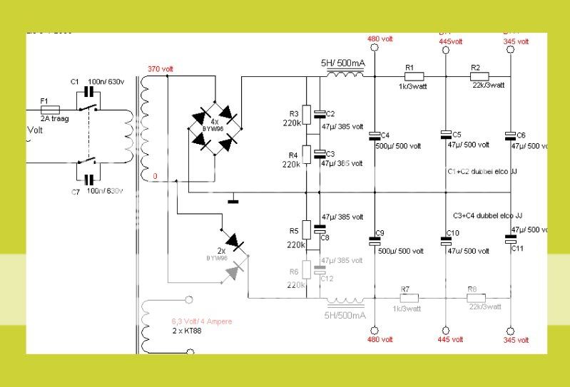
Original schematic:
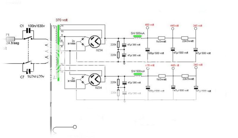
Modified schematic:
I have more voltage than in the original 370V vs 390V and at 0,5 A
Just clutching the straws.......
Cheers
H00hbt try to disconect Main transformer electrostatic shield from the ground point.(Top Metal plate)
BTW I dont see in your PSU schematic third Main ground lead conected to AMP chasis Top metal plate, but only two 230V/AC wires conected to Main Trans. over the Main switch.
Think to operate Tube Amps Without proper Main ground lead conected to metal chasis is Dangerous for Amps operator.(or anybody else)
Best Regards
Hello banat
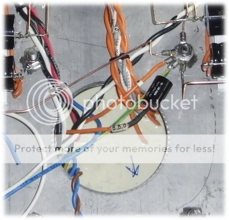
I have main ground from PX to chassis, green and yellow lead in picture.
Cheers
I think you swapped the diagrams! The modified one looks OK, except you show the ground connection by the first capacitor instead of the last one.
Your description sounds OK, except what about the other channel? Do you have a PSU ground bus down the middle of the chassis (as shown in the diagram), with connections branching off to each capacitor?
Can you look at the output with a scope? Is it hum or buzz?
Your description sounds OK, except what about the other channel? Do you have a PSU ground bus down the middle of the chassis (as shown in the diagram), with connections branching off to each capacitor?
Can you look at the output with a scope? Is it hum or buzz?
I think you swapped the diagrams! The modified one looks OK, except you show the ground connection by the first capacitor instead of the last one.
No, the top diagram is actually from the original designer "triode Dick". The posters version is the one with the problems.
Sheldon
http://www.triodedick.com/Bill/schema_voeding.GIF
Last edited:
h00hbt,
It's imprecise but pretty typical, to use the same symbol for safety earth and common. It's also pretty typical to show multiple earths or commons, and leaving it to the viewer to guess how they are connected.
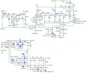
I'm always careful about how I do the commons and earth, because I hate hum. My hearing ain't what it used to be, but I can hear that. Also, it bugs me, because it's always a sign of poor design or execution. I recently built a phono amp, and any errors there will definitely cause hum. Therefore, I was careful to draw up a schematic which accurately shows the connections and how they are wired. I'll be presumptious and say that this is an example of what DF96 is looking for.
Note that the raw power supply is in a separate chassis from the regulator and amp. The safety earth is connected to the power supply chassis, which is then connected to the amp chassis. That is connected by a single wire to the amp star ground.
It's imprecise but pretty typical, to use the same symbol for safety earth and common. It's also pretty typical to show multiple earths or commons, and leaving it to the viewer to guess how they are connected.
I'm always careful about how I do the commons and earth, because I hate hum. My hearing ain't what it used to be, but I can hear that. Also, it bugs me, because it's always a sign of poor design or execution. I recently built a phono amp, and any errors there will definitely cause hum. Therefore, I was careful to draw up a schematic which accurately shows the connections and how they are wired. I'll be presumptious and say that this is an example of what DF96 is looking for.
Note that the raw power supply is in a separate chassis from the regulator and amp. The safety earth is connected to the power supply chassis, which is then connected to the amp chassis. That is connected by a single wire to the amp star ground.
Attachments
Last edited:
I think you swapped the diagrams! The modified one looks OK, except you show the ground connection by the first capacitor instead of the last one.
Your description sounds OK, except what about the other channel? Do you have a PSU ground bus down the middle of the chassis (as shown in the diagram), with connections branching off to each capacitor?
Can you look at the output with a scope? Is it hum or buzz?
DF96
No, I have wired the PS with a separate ground bus for each channel, just like in schematic.
Sorry, I havn´t a scope just multimeter.
Cheers
Haven't many of these Bills been built before? No need to redesign the power supply, and nothing wrong using two rectifiers in parallel. Your gnd bus is pretty solid.
Since you had a increase in hum when messing with the gnd connectinos, it seems obvious to keep looking into the gnd ckt.
Is the bias circuit on that circuitboard way up in the top corner? Isn't it rahter important that bias circuit is as close to the grid/cathode it is to control? Any chance of hum picked up on those long leads. Tho it shouldn't be a problem due to the nature of a symmetrical PP output canceling out such noise, but you never know...
Are the heaters for the output tubes floating as in the schem? Not that heaters on the output tubes should produce such hum, but by now you should try everything.
Have you tried to gnd the grids of the output tubes to see if the hum goes away? (Short to gnd with a capacitor to shunt AC to gnd). That way you can eliminate or determine the fault in the output stage.
Good luck, this can be frustrating...
Haven't many of these Bills been built before? No need to redesign the power supply, and nothing wrong using two rectifiers in parallel. Your gnd bus is pretty solid.
Since you had a increase in hum when messing with the gnd connectinos, it seems obvious to keep looking into the gnd ckt.
Is the bias circuit on that circuitboard way up in the top corner? Isn't it rahter important that bias circuit is as close to the grid/cathode it is to control? Any chance of hum picked up on those long leads. Tho it shouldn't be a problem due to the nature of a symmetrical PP output canceling out such noise, but you never know...
Are the heaters for the output tubes floating as in the schem? Not that heaters on the output tubes should produce such hum, but by now you should try everything.
Have you tried to gnd the grids of the output tubes to see if the hum goes away? (Short to gnd with a capacitor to shunt AC to gnd). That way you can eliminate or determine the fault in the output stage.
Good luck, this can be frustrating...
Hi SemperFi
Yes, you are right, many have been built before and it seams that there isn´t alot of problems with the design in general. I guess I will just work my way up the line and through the amp and se if I can make something out. Does seam strange that the hum whent up after re-wiring the ground bus so maybe the answer is there somewhere. Might just try to ground the grids and se, what value and V cap would I use?
Thanx
i would ground the inputs while looking for hum to make sure the hum is from ground loops. u mentioned that you disconnected the volume pots means that the inputs are floating and this can lead to instability, hum and oscillation.
I will connect them again and se how the level of hum behaves, thanks
Maybe easier to lift the coupling cap. If not the cap should be a value that will shunt the low freq hum to gnd, say 10uF.Might just try to ground the grids and se, what value and V cap would I use?
Thanx
WOOOOHOOOOO!!
NO HUM!! 0,0000VAC on both output terminals. Absolutly dead quiet. Sounds just great, a little held back and muffled like not quite burnt in, promissing though.
Don´t know what caused the hum probably a combination of things. I went through sirquit and all the solder joints and made new connections on several places to ground. The 6SN7 tube I used was really bad so I changed it.
Anyway, thank you all for your concern and good ideas, just shows what a great community this is.
Cheers
Now...MUSIC!!!!
Good - enjoy the music!
Later on, it might help if you rethink through what changes you made to fix it, and try to decide which particular change did the trick. In doing this you will learn more about grounding. People sometimes regard this as a black art, but in most cases it is simply applied physics!
Later on, it might help if you rethink through what changes you made to fix it, and try to decide which particular change did the trick. In doing this you will learn more about grounding. People sometimes regard this as a black art, but in most cases it is simply applied physics!
Good - enjoy the music!
Later on, it might help if you rethink through what changes you made to fix it, and try to decide which particular change did the trick. In doing this you will learn more about grounding. People sometimes regard this as a black art, but in most cases it is simply applied physics!
Hi DF96
I believe that good mechanical contact is crucial in all connections. I suspect that I maybe had a dodgy one or two.
I need to bias the tubes now, how do I do this? wich pinsdo i connect to the multimeter and how many mA should I have?
Thanks DF96 for you help
Cheers
Good for you.
Place the multimeter leads over the cathode resistor, 1ohm types, and adjust the pot for the corresponding tube till you get 50mV. According to schematic.
Hi SemperFi
Thanks
Cheers
- Status
- This old topic is closed. If you want to reopen this topic, contact a moderator using the "Report Post" button.
- Home
- Amplifiers
- Tubes / Valves
- Anyone care for some troubleshooting? Hum issue