Hello all
I've been enjoying Tube sound for years and have been lurking on this forum for sometime before Joining. I have no formal electronics training but have been reading everything in hopes of learning. I have exhausted all areas that I can think of in hopes of getting hands on training. The tech schools in my area almost laugh when I try to find a course to persue my hobby. I've ask the only shop in town that deals with Tube Equipment if they would take on an apprentise. I placed ads on local bulletin boards offering to pay someone to help me out. All this said my questions are these...
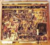
I bought a Sherwood S-8000 off E-Bay in hopes of starting out simple such as cap replacements so on and so forth. After recieving and seriously looking at the components, everything I thought I learned did not seem so clear. This unit has tons of white retancular resistors (I presume they are resistors) I'm lost as to what to do with them. Also I can find no articles pointing me as to where exactly are the coupling capacitors.
Now that everyone is through laughing at me. I asking for help on identifing all these components. Attached is the underside of my unit I want to learn on. Please don't turn me away!!
Thanks Steve
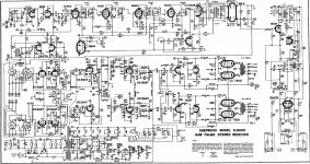
P.S. I also have have the complete Operational, Installation, and Service Manual. If anyone is wanting it Please E-Mail
I've been enjoying Tube sound for years and have been lurking on this forum for sometime before Joining. I have no formal electronics training but have been reading everything in hopes of learning. I have exhausted all areas that I can think of in hopes of getting hands on training. The tech schools in my area almost laugh when I try to find a course to persue my hobby. I've ask the only shop in town that deals with Tube Equipment if they would take on an apprentise. I placed ads on local bulletin boards offering to pay someone to help me out. All this said my questions are these...
I bought a Sherwood S-8000 off E-Bay in hopes of starting out simple such as cap replacements so on and so forth. After recieving and seriously looking at the components, everything I thought I learned did not seem so clear. This unit has tons of white retancular resistors (I presume they are resistors) I'm lost as to what to do with them. Also I can find no articles pointing me as to where exactly are the coupling capacitors.
Now that everyone is through laughing at me. I asking for help on identifing all these components. Attached is the underside of my unit I want to learn on. Please don't turn me away!!
Thanks Steve
P.S. I also have have the complete Operational, Installation, and Service Manual. If anyone is wanting it Please E-Mail
Attachments

Last edited:
"Attached is the underside of my unit I want to learn on."
If you were trying to attach a picture this is how to do it,
Too add a photo,
First click "go advanced" in the box below the "quick reply" message box. Doesn't matter if you decide half way through a message to do that, it carries it foward.
Then click "Manage attachements"
Click browse in the first box at the top and find your picture. Repeat for any more pictures.
Click upload... a message appears "uploading"
When complete, scroll down to the bottom of page and click "close this window"
The pictures should now be attached and when you post will appear. I don't think they show in message preview... they never used to anyway.
Make sure your pics aren't too big, a couple of 100k is plenty, and many object when they are massive and it alters the margins
It tells you in the attachments window what max sizes are allowed.
what jlsem said - tubed receivers of yore aren't exactly the easiest project to start with...
The little white/brown "coffin" shaped resistors are wirewounds made for power supply voltage dropping. These are probably the most stable of the lot and maybe ok. Only way to know is to check. Looks the coupling capacitors are the "black licorice" units. Looks like everything is marked, so it shouldn't be that hard to figure everything out. Of course with something this old, the power supply capacitors are the most likely to need replacement. The coupling caps could be leaky and the carbon comp resistors are probably out of spec.
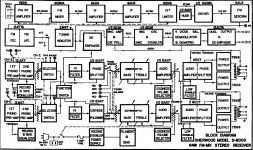
A Dynaco 70 (or just about any basic amplifier) would be an easier jumping off point since with the receiver you'll have to figure out what is the tuning section vs. the preamp section vs the amplifier circuitry. It's easy enough with some experience and common sense, but can be a little daunting at first.
The little white/brown "coffin" shaped resistors are wirewounds made for power supply voltage dropping. These are probably the most stable of the lot and maybe ok. Only way to know is to check. Looks the coupling capacitors are the "black licorice" units. Looks like everything is marked, so it shouldn't be that hard to figure everything out. Of course with something this old, the power supply capacitors are the most likely to need replacement. The coupling caps could be leaky and the carbon comp resistors are probably out of spec.
A Dynaco 70 (or just about any basic amplifier) would be an easier jumping off point since with the receiver you'll have to figure out what is the tuning section vs. the preamp section vs the amplifier circuitry. It's easy enough with some experience and common sense, but can be a little daunting at first.
Wow, can you say "rat's nest"?
I like your plan to learn by starting with a piece of equipment. Unfortunately, you may have made a less than optimal choice. Without well established knowledge, you will not be able to pick out individual components and know what they are for from that mess, nor will it be easy to trace in an organized way to draw up the schematic.
My 2c:
Start with a basic text on tube amps such as those mentioned over and over again on this site (Morgan Jones for example), follow that with an even more basic text on electronics (components, schematic reading etc.) and maybe some articles on measuring (using voltmeters, oscilloscopes, etc.). Scour this site for schematics and all the forum members discussions of them. Great knowledge and information there.
Then, and only then (well maybe about 2/3 of the way through that process) try one of two things. Either find a SIMPLE (and inexpensive) amp, preferably NOT point to point wired (unless it is very simple), and trace the schematic out. Draw it up, measure the voltages and be sure you know how to determine the components and values and what they are for, then post it here and have your work checked. Or, buy a simple kit and build it making sure you understand how the components on the schematic relate to the ones on the circuit board.
The rectangular white ceramic "blocks" are wirewound resistors, that rarely go bad. I'd concern myself with other parts. It appears that 2 power supply capacitors are visible side by side just below the power transformer. These visible bottoms should correspond to two aluminum, or cardboard covered "cans" on the top. You may want to consider replacing these, as they age. Be certain that they are discharged, before you work on them. Have you had the unit turned on? Does it work? If so, I wouldn't go changing parts, just for the sake of changing parts. Stay away from the RF and IF sections. If you randomly go changing parts in these areas, you may have trouble getting the FM and AM working again.
It looks like it has a two wire AC feed power supply. Be aware that this setup can kill you! Either switch it over to a properly grounded 3-wire setup, or only power it up through an isolation transformer.
It looks like it has a two wire AC feed power supply. Be aware that this setup can kill you! Either switch it over to a properly grounded 3-wire setup, or only power it up through an isolation transformer.
Last edited:
I've ask the only shop in town that deals with Tube Equipment if they would take on an apprentise. I placed ads on local bulletin boards offering to pay someone to help me out.
You might tell folks where you are. Someone here might be close enough to help a little.
Sheldon
Thanks My only problem is I'm kind of boxed in to this unit to work on (long Story). I have not had it plugged in since I bought it. I've read enough to know not to do this till I change out some capacitors. I starting small such as changing out all can capacitors (5) then work on the rest of the capacitors. I've also been checking the resistors in anticipation for replacing those that need it. At this time I'm not real concern about the tuner section,mainly wanting to acheive the best out of Pre and Main.
if I could isolate the tuner so as to have only pre and main that would work for me.
if I could isolate the tuner so as to have only pre and main that would work for me.
Attachments
That is a classic example of Hardwire Hell.
John
 Yeah. If that had been my first project I probably ended up with another hobby..
Wow - uhhhh Does it work? I would be tempted to turn it on in a test setup on the bench. Mabe using the light bulb trick in the power line to prevent doing damage. If it plays, let it run for a few days. If you are lucky it might reveal any problems and you could just do the mininum to make it usefull. The light bulb trick involves putting a 100watt light bulb in series with the line power cord. This limits the line power and can often save you from smoke. Allows a chance to run around with a voltmeter and check the operation.
Don't touch the RF section unless you have the knowledge and test equipment to correct the faults you are likely to introduce. Sorry to sound negative, but every week or so someone pops up and says he has "re-capped" an amplifier (often his first ever soldering) but now it doesn't work, so can we help? Audio is much easier than RF!
Thanks all for info. I will start with the simple recaps and work my way into what I feel comfortable with. I have no way of knowing if this amp works or not I was only assured that the transformers good. This is my learning project, time is irrelevent as to how quickly this gets done. So I appreciate any advice givin to me. This is forum has been my classroom. I hope someday I have something usefull to contribute to this forum.
Thanks All
Thanks All
- Status
- This old topic is closed. If you want to reopen this topic, contact a moderator using the "Report Post" button.
- Home
- Amplifiers
- Tubes / Valves
- Help identifying components