Hi there,
I recently found some time to continue work on my PP1C version - which unfortunately still exists on paper only ...
...
As I would like to fit a tube-based PSU, excessive playing with Duncanamps' PSUD led to the following, showing only the supply for one channel each:
The "standard" solid state power supply circuit:
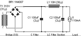
Output: approx. 409V DC @ 110mA
Hum: 17mV p-p
A GZ34-based supply w. choke input:
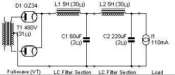
Output: approx. 413V DC @110mA
Hum: 12mV p-p
Will this work or do I forget something important?
Second question: Planning to buy only one (custom-wound, expensive) power transformer with twice the current capability and drive the supplies for both channels from the same transformer winding - bad idea?
A first version with EZ81 simulated fine in PSUD, but cross-checking with the datasheet showed my plans to be far out of SOA...
Thanks for your ideas and comments,
Andreas
I recently found some time to continue work on my PP1C version - which unfortunately still exists on paper only
...As I would like to fit a tube-based PSU, excessive playing with Duncanamps' PSUD led to the following, showing only the supply for one channel each:
The "standard" solid state power supply circuit:
Output: approx. 409V DC @ 110mA
Hum: 17mV p-p
A GZ34-based supply w. choke input:
Output: approx. 413V DC @110mA
Hum: 12mV p-p
Will this work or do I forget something important?
Second question: Planning to buy only one (custom-wound, expensive) power transformer with twice the current capability and drive the supplies for both channels from the same transformer winding - bad idea?
A first version with EZ81 simulated fine in PSUD, but cross-checking with the datasheet showed my plans to be far out of SOA...
Thanks for your ideas and comments,
Andreas
Your GZ34 version should work and it will probably sound better than Solid State rectifier. You can make it with just one choke, LC filter.
The power transformer having a rating of twice the actual current consumption is an excellent idea, though expansive.
Having a separate power transformer and regulator for each channel will give you what is called "dual mono". It's the best approach, though quite expansive.
The power transformer having a rating of twice the actual current consumption is an excellent idea, though expansive.
Having a separate power transformer and regulator for each channel will give you what is called "dual mono". It's the best approach, though quite expansive.
For a PP amp, you will probably be happy even with a much smaller inductance choke, preferably low DCR.
Use PSUD to simulate also the step response, say change load from 100 to 150mA after a few seconds.
I am a little sceptical to the choke input (first LC). It may be difficult to get right.
Svein.
Use PSUD to simulate also the step response, say change load from 100 to 150mA after a few seconds.
I am a little sceptical to the choke input (first LC). It may be difficult to get right.
Svein.
Hi there,
I found the time to simulate the power supply step response today, here are the results:
PP1C power supply by A.Wright
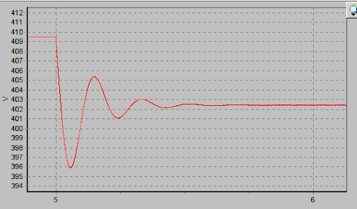
A load change from 110mA to 150mA causes the output voltage oscillation shown, the data evaluate to a frequency of 5,5Hz and a decay time of about 0,5s.
The GZ34 supply
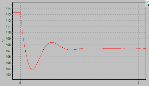
This one oscillates at 3Hz for about 0,5s as well after a step load change.
When playing around with PSUD, I found a few "stable" configurations which did not oscillate at load changes, but they involved large capacitances after the rectifier - not exactly what one wants with tube rectification.
As the circuit is Class A and will have a quite constant current draw, I am not going to worry much about the simulation results - especially as the original supply exhibits the same behaviour...
Greetings,
Andreas
EDIT: A dummy load is absolutely necessary for measurements with tube rectifier and choke filtering - The german surplus electronics distributor Pollin (www.pollin.de) currently has DALE high power resistors (up to 50Watts) for sale quite cheap - I will get some of them and mount them on a heatsink...
I found the time to simulate the power supply step response today, here are the results:
PP1C power supply by A.Wright
A load change from 110mA to 150mA causes the output voltage oscillation shown, the data evaluate to a frequency of 5,5Hz and a decay time of about 0,5s.
The GZ34 supply
This one oscillates at 3Hz for about 0,5s as well after a step load change.
When playing around with PSUD, I found a few "stable" configurations which did not oscillate at load changes, but they involved large capacitances after the rectifier - not exactly what one wants with tube rectification.
As the circuit is Class A and will have a quite constant current draw, I am not going to worry much about the simulation results - especially as the original supply exhibits the same behaviour...
Greetings,
Andreas
EDIT: A dummy load is absolutely necessary for measurements with tube rectifier and choke filtering - The german surplus electronics distributor Pollin (www.pollin.de) currently has DALE high power resistors (up to 50Watts) for sale quite cheap - I will get some of them and mount them on a heatsink...
Last edited:
- Status
- This old topic is closed. If you want to reopen this topic, contact a moderator using the "Report Post" button.
- Home
- Amplifiers
- Tubes / Valves
- Power supply for PP1C - sanity check