Hi all tube lowers!
I have a question. I am about to build Blue Velvet preamp from Dick Olsher and Kara Chaffee (http://www.blackdahlia.com/html/tip_44.html), which runs one 6SN7 per side. Looking at the schematics, I see the power supply to be 12 volts DC on the heaters for each 6SN7. Is this corrects? Should not that be two heaters in series? Or 6 volts? Am I missing something?
Thanks for your help,
Ed
http://www.blackdahlia.com/html/tip_44.html
The filament supply seems very inefficient, I suppose the idea was at least partially to control inrush current when the filaments are cold. In 25+ yrs I have never had a 6SN7 fail due to a filament burning out so it seems wasteful at best.. You could wire the pair in series and use a single regulator with a 1N4002 in the ground leg to get ~12.6V..
I have other reservations about this design, really the only good thing I see about it is that it is overall non-inverting.. The anode follower with feedback around represents a severe load on the plates of both triodes in this design and would result in an unnecessarily large amount of distortion particularly in the first stage which has no feedback around it.
The 6SN7 could be employed in a simple resistively loaded circuit with the other half serving as a cathode follower.. I also like "trendy" SRPP based 6SN7 line stages as well, mainly because... err.. well, they're trendy.. And I actually think they sound pretty good too.. Technically it is not the best choice, but then neither is the Velvet..
I have other reservations about this design, really the only good thing I see about it is that it is overall non-inverting.. The anode follower with feedback around represents a severe load on the plates of both triodes in this design and would result in an unnecessarily large amount of distortion particularly in the first stage which has no feedback around it.
The 6SN7 could be employed in a simple resistively loaded circuit with the other half serving as a cathode follower.. I also like "trendy" SRPP based 6SN7 line stages as well, mainly because... err.. well, they're trendy..
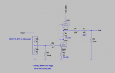
And I actually think they sound pretty good too.. Technically it is not the best choice, but then neither is the Velvet.. Here's that SRPP design I talked about in my last post, hardly what I would call the optimum design, but it does sound very good, is very simple and has a reasonable amount of gain for use as a line stage. (Generally a bit less than 20dB.)
The omission of a cathode bypass cap was deliberate in order to reduce gain, and eliminate the colorations a cheap electrolytic adds to the path.
I prefer the unbypassed cathode resistor - if you need more gain be sure to use a high quality electrolytic here.
Note that this design is inverting if that is important to you. (Can always swap speaker leads.)
A power supply capable of providing 330V - 360V of ripple free B+ at 20mA per stereo pre-amplifier is required. Filaments may be AC or DC heated, note that the filament to cathode insulation is running relatively near the ragged edge, and should be floated about 90 - 100V above ground to reduce stress to acceptable limits. (I've never had a tube fail in this circuit.) This becomes an issue with plate voltages above 360V. You could also split the upper and lower sections into separate 6SN7 or even use 6J5s and power the lot off of two separate filament supplies, but this has never proved necessary in my experience even at plate voltages of 400V. (Which is acceptable in this design)
Good quality parts will get you IMHO a very good sounding line stage and depending on tubes typically <0.05% thd at line levels of a couple of Vrms or less into a 100K load. Very quiet too.
Remember it's trendy.. (Or is it - the first one I built was >10 years ago..)
Attachments
Last edited:
I'm with Kevink here...
Starting with the power supply, I would use capacitor input followed by a Maida regulator (ancient application note from National Semiconductor). I hear the choke input supplies are tough to manage at low currents, but I do openly admit that I have no personal experience with this. The B+ supply as drawn is incredibly inefficient.
The filament supply relies on resistors that will have to be tweaked. I find that pretty silly. I'm guessing the purpose of the resistors is to implement soft start but they do more harm than good in my opinion. I'd use an LM317 for the filament and rely on its internal current limiter to limit the filament current during start-up. Or if you really do want the soft start, see page 16 of the LM317 datasheet.
The amplifier is a good topology, however, I do have some reservations about how it's implemented. The first tube operates as a regular common cathode stage. The second is set up as an inverting amplifier with a gain of approx 1 V/V. I've seen this topology referred to as an anode follower, though, some people seem to not like that designation... I use a stage like that as a driver for a 300B in my current power amplifier design. I like it. It has a very natural or neutral sound. Anyway.....
First off, the anode resistors dissipate 0.49 W each. The resistors are spec'ed to be 1 W types. This means that they'll be screaming hot (well above 100 deg C). I suggest changing those to 2 W or 3 W types. The resistors also seem to be very low in resistance. I'd have expected something around 20~50 kOhm, but of course B+ would have had to be raised to accommodate the increased voltage drop. Something like 22 kOhm, 7 W and 375 V B+ would give the same operating point but much higher gain of the first stage and better control of the gain in the second stage (increased loop gain).
Secondly, the second stage loads the first stage very heavily. I suggest using 68 kOhm for R3, R4 rather than the current value of 6.8 kOhm.
I don't like to have pots controlling the bias. Pots have a nasty way of failing. Either make the cathode resistors 330 Ohm or use two red LEDs in series. The LEDs will give you roughly 3.5 V on the cathode.
Oh... And add an input cap and grid leak resistor (1 MOhm) to ground on the input tube.
In my humble opinion (and yes, I am opinionated): Good topology, but it could use a redesign.
~Tom
It says adjust R1 and R2 for 6.3 Volts.
Craig
Sorry, I missed that part, I just assumed it was 12V since it uses 12V regulator. My bad.
Why not use only the first stage? Plain & simple & good.
The first stage by itself has rather high output impedance. Hence, its gain will be very load dependent. The output impedance of the second stage is much lower due to the local feedback loop.
If you need more gain, you can also set up the second stage to provide more than unity gain. The gain of the second stage is roughly -R4/R3. (The minus sign refers to the 180 degree phase shift).
~Tom
I have other reservations about this design, really the only good thing I see about it is that it is overall non-inverting.. The anode follower with feedback around represents a severe load on the plates of both triodes in this design and would result in an unnecessarily large amount of distortion particularly in the first stage which has no feedback around it.
Interesting circuit- mediocre distortion, poor power supply rejection. Certainly worthy of "high end audio."
At least, the author is not afraid to do something unusual.
But is that a good thing? The task here is a very simple one, moderate voltage amplification at line levels and a low output impedance. That's so easy to achieve with simple, conventional circuitry that one wonders what the motivation is to do something complex with worse performance.

Interesting circuit- mediocre distortion, poor power supply rejection. Certainly worthy of "high end audio."
I think we've probably both seen worse..
You forgot unnecessarily inefficient..
But is that a good thing? The task here is a very simple one, moderate voltage amplification at line levels and a low output impedance. That's so easy to achieve with simple, conventional circuitry that one wonders what the motivation is to do something complex with worse performance.
Precisely to be complex.
Velvet evokes soft and (p)lush, kind of how I imagine this design might sound.. Very euphonic with a harmonic excess of riches brought about by a lot of lower order harmonic distortion.. Damn, I might have to build one...
Just kidding... At the face of it this might be a deliberate tone control...
Last edited:
To learn from own mistakes?
Yes.
Given what I suspect was the intent of the original designers, I don't believe this would be perceived as a design mistake. I'm quite sure it was deliberate and to a specific end sonically speaking. It is what I call a "tone control" - tongue in cheek..
SY's comment in a previous post about high end audio was pretty much spot on in my experience. (Largely negative..)
Last edited:
I actually don't think the circuit is that horrid. I'd throw it through the design cycle once more as I said earlier. But there really is no reason this amp topology couldn't deliver moderate voltage gain and low(-ish) output impedance.
Redo the power supply. Use CCS loads, LED bias and jack up R3, R4 to 100 kOhm and you have a decent starting point. You should get close to 20 V/V gain and an output impedance on the order of 350 ohm through the audio range.
~Tom
Redo the power supply. Use CCS loads, LED bias and jack up R3, R4 to 100 kOhm and you have a decent starting point. You should get close to 20 V/V gain and an output impedance on the order of 350 ohm through the audio range.
~Tom
I actually don't think the circuit is that horrid. I'd throw it through the design cycle once more as I said earlier. But there really is no reason this amp topology couldn't deliver moderate voltage gain and low(-ish) output impedance.
Redo the power supply. Use CCS loads, LED bias and jack up R3, R4 to 100 kOhm and you have a decent starting point. You should get close to 20 V/V gain and an output impedance on the order of 350 ohm through the audio range.
~Tom
But, but, but..
You know what you're doing, and you understand the difference between designing for a technically rigorous result, and something that is designed to add a certain amount of deliberate coloration. The designers are well known in audio circles and while the design from an engineering viewpoint as implemented is not satisfactory from our standpoints I believe it was largely deliberate.. (The rules we engineers apply to a design and design process don't always apply to "high end" designs. Art is all, science is...) IMHO It was designed for something other than what most of us aspire to, or (devils advocate) it was designed by people who really don't understand how tubes work. Both are probably true..Yeah... "High End"... I could launch into a long rant about that. I'll refrain at this time...
An op-amp with a diode in the feedback path will also create "tube sound" to some people. Heck, an LM741 and a 1N4148 are cheaper than the ceramic socket for a 6SN7. No need to mess with high voltage either.
~Tom
An op-amp with a diode in the feedback path will also create "tube sound" to some people. Heck, an LM741 and a 1N4148 are cheaper than the ceramic socket for a 6SN7. No need to mess with high voltage either.
~Tom
- Status
- This old topic is closed. If you want to reopen this topic, contact a moderator using the "Report Post" button.
- Home
- Amplifiers
- Tubes / Valves
- Blue Velvet preamp