A typical PP Williamson design amp has B+ connected to the output transformer center tap. from there, DC runs thru the tranny. Once it leaves the tranny, a connection is made to the plates of the P+ and P- side of the output stage directly. Basically, this results in the opportunity for the output stage in attempting to reproduce DC.
Take the case of a 2.5K output transformer. If I were to install a 6uf film capacitor in between the B+ power supply and the B+ connection on the tranny, I would reduce the electromotive force below 10hz while leaving the electromotive force above unaffected.
Why wouldn't I want to do this?
Also, with todays miniature surface mounting and micro connection technology wouldn't this also be an alternative way of controling the main bias power supply? changing the values of such a capacitor would change the slope on what is blocked. block 1hz (63uf cap) and I reduce my electromotive force by n%. Block 2hz (31uf cap), and I reduce my electromotive force by n%*n.
Why bring this up? I have an mono amp with 10 output tubes per amp. It has 10 individual bias trim capacitors mounted on a small PC board. It would be a lot easier for me to use an inline film capacitor to block DC, 1hz, 2Hz, etc at the 6db slope rate to change the overall bias current rate on the plate side and then fine tune with the individual bias trim capacitors than to try to remove and replace the micro trim bias pots.
Pro's would be an easy master bias control point. Cooler tubes that are not trying to produce DC. Lower noice floor as a result of the 6db slope effect (60 hz hum is reduced at the 6db slope rate) an hipass capacitor exhibits. cons would be reduce bias current as a result of the 6db slope effect......but I want that.
Thoughts and ideas on making this work.
Last edited:
Err....
It wouldnt have +B on either the Tx OR the plates of the valves if you shoved a cap in the supply to the centre-tap!
Therefore, It Wouldnt Work At ALL!
You HAVE to have DC flow through the valve for it to function!
An inline capacitor would not totally dead stop DC. It will just reduce it based on the cap value and the targeted frequency at a slope rate.
so if I wanted a 5% reduction at 0hz, it will take a cap at xHz of n value. DC would be reduced, bias will go down.
Could you draw a circuit diagram? Some things you say don't immediately make sense.
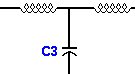
center tap of transformer normally connected to B+ gets an inline 63uf 630volt film capacitor. Targeted frequency is 1hz. DC gets reduced a small percentage as a result of the slope effect an inline hi pass capacitor has.
we basically increased the circuit impedance of DC with out increasing the circuit impedance significantly within the audio band (20hz - 20khz).
Attachments
An inline capacitor would not totally dead stop DC.
After a whole lot of studies and thinking you may invent parafeed. Cannot guarantee it though.
No, I don't understand it either - even with a partial diagram.
A capacitor does not pass DC. It passes AC and/or pulses. The average current (averaged over a sufficiently long period) is zero.
A transformer also does not pass DC. Only the AC component of the primary signal appears in the secondary. However, both the primary and secondary can separately pass DC.
Could you draw a diagram of a complete output stage with your idea? Then we can perhaps understand where you are going wrong and explain it to you.
"opportunity for the output stage in attempting to reproduce DC."
Electrical components are not opportunistic nor does a transformer "reproduce" DC: no current flows in the secondary. What you describe will not work.
I think you are trying to re-invent parallel feeding the output tubes, but you have the topology all wrong and don't understand basic AC and DC circuit theory. The OP tubes still need a DC path between ground and B+. You need a plate choke or a resistor to provide a load for the OP tubes then RC couple the OP tubes to the primary of the OP transformer. Now you have an OP transformer with no DC flowing in the primary.
An inline capacitor would not totally dead stop DC. It will just reduce it based on the cap value and the targeted frequency at a slope rate.
so if I wanted a 5% reduction at 0hz, it will take a cap at xHz of n value. DC would be reduced, bias will go down.
Maybe it would be clearer if you could work through your example above and calculate what cap value it would take to reduce B+ by exactly 5%?
Thanks,
Michael
excellent comments.
So now I'm thinking the ideal place to do this is in the secondary that feeds the bias supply rectifier. I can just use a small autoformer in the bias supply secondary to lower the bias supply AC voltage level the small variation I need without having to desolder and replace 10 bias trim pots X 2 amps.
So now I'm thinking the ideal place to do this is in the secondary that feeds the bias supply rectifier. I can just use a small autoformer in the bias supply secondary to lower the bias supply AC voltage level the small variation I need without having to desolder and replace 10 bias trim pots X 2 amps.
Ideal place to do what? We still don't understand what you think you are trying to achieve. You seem to have switched from adding a capacitor in your HT supply, to adding an autotransformer in your bias supply. Neither makes any sense, unless we have seriously misunderstood you.
Please draw diagrams - fairly complete, not just a little sample.
Please draw diagrams - fairly complete, not just a little sample.
excellent comments.
So now I'm thinking the ideal place to do this is in the secondary that feeds the bias supply rectifier. I can just use a small autoformer in the bias supply secondary to lower the bias supply AC voltage level the small variation I need without having to desolder and replace 10 bias trim pots X 2 amps.
Hmm....
I think you NEED to show us a schematic of your amp As It Currently Is...
And a schematic of your amp With Your Proposed Modification....
Your amp has Individual Bias Pots FOR A REASON!
--This is to Match Each Valve to its neighbour. Valves are Never exactly the same--Even so-called, Matched valves. All AGE differently!
What are you trying to achieve...?
--A master bias pot to set them all....??
I Seriously Suspect you could cause serious damage either to the Valves or other parts of the amplifier if you start messing round with the Bias Supply by shoving a cap in series with it!
--You HAVE TO have a DC Voltage for Neg. Bias, or the valves will soon self-destruct!

Please Please, Before you do Anything Revise your knowledge of AC and DC cuurents in circuits--Particularly DC!
--I'm not being funny, just trying to save you what could well be a VERY EXPENSIVE mistake!
Last edited:
"Why attempt to reproduce DC in a tube amp?"
Because tubes pass only DC. No DC, no tube amp. The DC is modulated into pulses, but it's always only passing current in that same single direction. Then the DC "bias" "component" or whatever you want to call it is "blocked" so only the "pulses" are presented to the speaker or the next tube's input.
Caps block DC when they are inline and they "smooth" DC when they are parallel to the DC. If you place one inline with the B+ you block it and prevent the related tubes from functioning.
This is not the place to argue about what is meant by "DC". There has already been a long thread about that. Valves are unidirectional, which is not necessarily the same as DC. It makes more sense to define DC as meaning frequencies around 0Hz in a Fourier analysis, except for elementary textbooks for newbies.
- Status
- This old topic is closed. If you want to reopen this topic, contact a moderator using the "Report Post" button.
- Home
- Amplifiers
- Tubes / Valves
- Hipass filter to control master bias? - Why attempt to reproduce DC in a tube amp?