I've been very slowly gathering parts for my build and stumbled upon this. It looks like Power Drive (Tubelab) meets the Synola. I'm sort of a"paint-by-number" builder and no expert. Your opinions on the circuit would be greatly appreciated.
Ciao
An externally hosted image should be here but it was not working when we last tested it.
from FORUM - Synola 509 mit Mosfet - eine Verbesserung?
Have you already build this circuit? The driver stage for the output tube has been the issue with the original Synola amp, it looks like this circuit at least improves on that issue. I think I would remove the 2,2k/3W resistor from the mosfet's emitor as it might introduce distortion when the screen grid is drawing more current.
Hi folks!
After three months my power transformers are almost done so I should be able to start building my mono blocks really soon.
In the mean time I have been playing around with this amplifier and I have now settled for a very nice, KISS approved, circuit. You can download the circuit here: http://www.hostpalace.nl/meuk/Update.pdf
My goal was to experiment a lot and to end up with a relative cheap amplifier. That goal has been reached, I am now able to drive the screen grid with only half a ECC82 tube, without going into distortion. In my circuit I have used an ECC823 because I wanted to play around with this two faced tube, of course it can be replaced with a ECC82 and a ECC83.
I suspect that good quality parts (tubes, trannies, R's, C's and L's) for a stereo amplifier would only cost €400. I will soon find out because I intend to build a stereo version as soon as possible! The costs can be even lower by using SS rectifiers and dropping the sepparate bias supply.
I have finished one channel and I am test running it right now. It performs very well so far, however the tubes are brand new and it's only running for about two hours so I have to re-judge the amp as soon as I have build a stereo version
Hi lechuck
I have some PL519 and i want to build you SE amp, but i can´t get to the schematic.
can you please post a copy or send a copy
BR/ skjold
I am wondering if the ECL86 would be a better tube as a driver for this project rather than a ECL82/6MB8 the triode of a ECL86 has a Mu of 100 and the cathode current higher for the Pentode section of the tube, I have read of a guy driving a pair of EL509 in PSE mode at 40mA each tube plate current so the ECL 86 pentode stapped in triode has 55mA of cathode current .
There is logistic problems with ecl82 and particularily ecl86. They are not made anymore, all you can find is remnants of old stock, expensive and in many cases tubes rejected earlier.
I would suggest using a new production or at least something that is more available, pcl84 ecl80 comes to my mind. Of new production EL84 is a good alternative, trides ecc81/82/83/88 and to some extent ECC99 and 12bh7 is new production.
I would suggest using a new production or at least something that is more available, pcl84 ecl80 comes to my mind. Of new production EL84 is a good alternative, trides ecc81/82/83/88 and to some extent ECC99 and 12bh7 is new production.
I know the EL84 is a good alternative and ECC81 are still available and NOS ECC81 are much cheaper EAR schematic online since 1994 could use PCC88 or ECC88 for both ,these are also still in production and capable of 25mA cathode current for the Grid of the EL509 as its quite hungry in enhanced triode mode PL509 is just a EL509 with 40v heaters and not to expensive
Don't do it! About nearly 20 years ago I've also built a screen driven PL519 amplifier alongside the Svetlana bulletin. Driven by the same thoughts as yours', I've tried the PCL86 as the voltage amplifier/buffer device - with bad results. I've found out the PCL86's triode, which is half an 12AX7, wasn't able to deliver the signal level the PL519's screen demands. The triode in the PCL82, which is about half a 6SL7, proved to be more up to task by far. Thus I have been wondering why the Synola could work at all. I phoned the designer to find the solution, but it wasn't too satisfying to me.
The schematics I was using was a modified Danielak/Svetlana design, as I've found several design flaws. Yes, it has been said yet, Danielak's is based on simulation only, most probably using an inappropriate EL509 model. I never managed to draw 12 watts out of my amplifier, 8 to 9 watts are more the real world, using my modified design. Danielak's didn't get me near to this at all.
Best regards!
The schematics I was using was a modified Danielak/Svetlana design, as I've found several design flaws. Yes, it has been said yet, Danielak's is based on simulation only, most probably using an inappropriate EL509 model. I never managed to draw 12 watts out of my amplifier, 8 to 9 watts are more the real world, using my modified design. Danielak's didn't get me near to this at all.
An ECL80 won't do, as it is common cathode and the pentode is very tiny (plate dissipation rating only 3 watts).I would suggest using a new production or at least something that is more available, pcl84 ecl80 comes to my mind.
Best regards!
PL519 EL84
Hi lechuck. do you have the schematic of this now ?
Thanks
I have just finished building a single ended amp based on the Synola design. <snip>
Hi lechuck. do you have the schematic of this now ?
Thanks
Don't do it! About nearly 20 years ago I've also built a screen driven PL519 amplifier alongside the Svetlana bulletin. Driven by the same thoughts as yours', I've tried the PCL86 as the voltage amplifier/buffer device - with bad results. I've found out the PCL86's triode, which is half an 12AX7, wasn't able to deliver the signal level the PL519's screen demands. The triode in the PCL82, which is about half a 6SL7, proved to be more up to task by far. Thus I have been wondering why the Synola could work at all. I phoned the designer to find the solution, but it wasn't too satisfying to me.
The schematics I was using was a modified Danielak/Svetlana design, as I've found several design flaws. Yes, it has been said yet, Danielak's is based on simulation only, most probably using an inappropriate EL509 model. I never managed to draw 12 watts out of my amplifier, 8 to 9 watts are more the real world, using my modified design. Danielak's didn't get me near to this at all.
Best regards!
I experienced the Synola an can only say it works very well.
However I still was concerned about the driver capability and when I built my own version of this amp I used the PCL82.
The amp is decribed here: http://www.diyaudio.com/forums/tubes-valves/211254-magnificent-television-tubes-94.html#post5254991
Post #931
As far as I could find out, power is mainly limited by clipping in the input stage which is somehow constricted regarding its operating point due to the DC-coupling.
Best regards
Philipp
Hi Kay,
Do you have a copy of your modded Danielak's schematic with the PCL82 or ECL82?
before I head down the EL84 - ECC88 track
Thanks
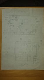
Of course. Here's my hand-drawn circuitry.
The main differences from Danielak's design are:
- In Danielak's the bias adjustment trimpot also impacts the amplifier's gain, 'cause it is in the GNFB loop. This appeared absolutely unwanted to me.
- I've found severe current take over issues when the PL519's screen was high and plate was low level, as described several times above. To cure this, I lowered both cathode and screen idle voltages.
- I didn't find any use in tying the bottom side of the PCL82's pentode's cathode resistor to the triode's cathode's network, so I returned it to ground.
- I've also found out that there's no reason for the PL's plate load of being more than 2400 ohms.
All the other differences mainly are according to my taste.
Here's a link to the amplifier when I presented it at a German tube lovers' meeting in March 2005. And here's the Synola 509 prototype. Reinhard Seyer from Hamburg, the designer, also has been at this meeting.
Best regards!
Attachments
Hi Kay,
How much gain peak to peak is now in your driver circuit, as the 509 grids not only need quit a bit of current they also need a lot of input voltage to drive the 509 to good output levels
I was wondering if the voltage on the plate of the 509 was increased to 500v and current load pushed back to 80mA the 509 could infarct deliver 12-14 watts output ?
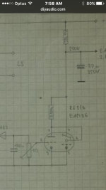
Thanks for the schematic ! What is the tube type introduced in the feed back loop And can't read the plate R value or adjustable pot value that is the the right of the 100uf capacitor Image include Interrelated also in the adjustment needed within this Feed Bsck loop ?
Thanks
How much gain peak to peak is now in your driver circuit, as the 509 grids not only need quit a bit of current they also need a lot of input voltage to drive the 509 to good output levels
I was wondering if the voltage on the plate of the 509 was increased to 500v and current load pushed back to 80mA the 509 could infarct deliver 12-14 watts output ?
Thanks for the schematic ! What is the tube type introduced in the feed back loop And can't read the plate R value or adjustable pot value that is the the right of the 100uf capacitor Image include Interrelated also in the adjustment needed within this Feed Bsck loop ?
Thanks
Attachments
Hi Perfectusaudio,
it was in 2005 when I designed and built this amplifier. It hasn't been very much in use since then, sitting apart most of the time. I didn't write down all of my measurements, so I'd have to put it back to my bench to answer your 1st question. Most probably you're right in your assumption that a higher plate voltage may ease the PL's task.
To your 2nd question: The tube shown in the left part of my drawing doesn't have anything to do with the amplifier itself, and it doesn't impact the GNFB loop in particular. It is just a volume indicator, using the nice little EAM86/6GX8 tuning indicator that easily can cope with the relatively small output voltage this amplifier is able to deliver. Btw, the related cap's value is 100nF instead of 100µF, the trimpot's is 1MOhms, the plate resistor's is 220kOhms. Sorry, but I don't own a, maybe better readable, computer generated drawing.
Best regards!
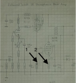
As said before, it's been a long time since I built this amplifier, and my memory has lost most of the details. I don't even remember the exact plate load value, it is either 1k7 or 2k4.
I didn't do any distortion measurements, as I didn't have any equipment for it in those days. Just an o'scope and a function generator. To make up for it, I'd have to put the amplifier on my workbench again. Honestly, I don't have any time for that, as there are many more promising projects waiting to become realized. And I've completely lost any interest in inefficient amplifier designs (triodes, SE etc.).
Sorry, but I can't help you more.
Best regards!
Resistor Values - arrows 1& 2 please on attachment?
Hi Perfectusaudio,
it was in 2005 when I designed and built this amplifier. It hasn't been very much in use since then, sitting apart most of the time. I didn't write down all of my measurements, so I'd have to put it back to my bench to answer your 1st question. Most probably you're right in your assumption that a higher plate voltage may ease the PL's task.
To your 2nd question: The tube shown in the left part of my drawing doesn't have anything to do with the amplifier itself, and it doesn't impact the GNFB loop in particular. It is just a volume indicator, using the nice little EAM86/6GX8 tuning indicator that easily can cope with the relatively small output voltage this amplifier is able to deliver. Btw, the related cap's value is 100nF instead of 100µF, the trimpot's is 1MOhms, the plate resistor's is 220kOhms. Sorry, but I don't own a, maybe better readable, computer generated drawing.
Best regards!
Attachments
Thanks, as I have just 3 Siemens EL509 to experiment with , also have a spare 2.5k and 3.5K transformer .
Mullard PCL82 and custom made small from Bridge - HV PCB that are good for 15A 1200V, IXYS, Ultrafast, Soft Recovery (HiPerFRED) Epitaxial Diode (TO-220AC package) or any T0 -220 package style diodes Board size 30mm x 60mm
Mullard PCL82 and custom made small from Bridge - HV PCB that are good for 15A 1200V, IXYS, Ultrafast, Soft Recovery (HiPerFRED) Epitaxial Diode (TO-220AC package) or any T0 -220 package style diodes Board size 30mm x 60mm
Hi, this is an old thread but do you have the schematics I may try to build a singl
I have build a amp based on the Synola schematics. The distortion that you are hearing is very distinct and it's origin is in the tube that drives the screen grid on the PL519. When I first build the Amp I used a paralleled 8CG7 (kinda 6SN7 tube). This tube wasn't able to supply the current needed for screen drive and started distorting at aprox. 1W output power.
I have replaced the 8CG7 with a EL84 and now this limitation, and it's ugly distortion, is gone.
You can find the schematics of the amp here: 404 - Kan bestand of map niet vinden.
One side note: This amplifier sounds so incredibly good that one MUST build it. I am using it to drive a pair of Jamo Concert 11's. It has more than enough power for these speakers and the soundstage is unbelievable realalistic! This amp will blow away 30K+ commercial amps!
- Status
- This old topic is closed. If you want to reopen this topic, contact a moderator using the "Report Post" button.
- Home
- Amplifiers
- Tubes / Valves
- EL509 (JJ) or PL519?