Hi tubelab,
another point to consider is to use considerable g1 auto prebiasing when applying g2 drive, since it helps maintaining op point stability a lot. Especially with xL509, which has a bad tendence for thermic runaway when operated near its dissipation limits especially when g2 is severely loaded additionally by current takeover from the anode on low voltage anode swing (I learned this lesson when plotting several samples; it just emphasizes what you wrote in your previous article in this thread).
IIRC, TdP in his lecture even insisted on doing it by a cathode resistor autobiasing (for g1) to get the needed reliable regulation, or at least using mixed fix and auto bias. He went to some lengths talking about the rather large tolerances across NOS and new production xL509 types, even within the same production batch.
Regards, Tom
Driver stage weakness you say? Like?
I see that by replacing the CF-driver tube ECC82 to parallel connected 6N6P and biasing it to essentially higer standing current, most of the driving problems would be solved.
I have used 6N6P as a CF-driver with hi-mu connected GU50 which had the dynamic input resistance of some 300...330 ohms and the results were very good.
A Mosfet would do this job even better, but in my opinion, then we are not anymore involved in real tube amplifiers and I leave these constructions to other designers.

The JJ EL509 claims a 700 volt rating on the screen grid.
What JJ claim and what works in real life is FAR FAR away from each other.
Horrible tube in my opinion, they blow if the screens have more than 250V.
700V? BULLS**T.
Regards, Allen
Horrible tube in my opinion, they blow if the screens have more than 250V.
I have heard that, but since I have no first hand experience I didn't want to say it.
So it seems that JJ just copied selected bits of an old data sheet without knowing what they were printing. The JJ may well be a copy of an old EL509 sweep tube. No sweep tube that I have ever met will work with 450+ volts on the screen in pentode mode. Some survive in triode. So, if this is true the JJ may work in screen drive mode. Again, the only way to know for sure is to try it.
I have also built this amp for a friend, using Ei EL519 tubes. It has a very clean sound with amazing bass, giving more than 10 Watts/ch. But, if overdriven, strange things happen. Distortion does not sound like any SE triode amp, but appears suddenly, along with some cracking noises. (checked with ESL-57 Quad speakers).
Hi adam2a3,
Which one? The Bob D one or the Synola?
Tom
I have also built this amp (...)
Which one? The Bob D one or the Synola?
Tom
Hello Tom,
it is the Bob D amp I tried. If this power is ok with your speakers it is an excellent amp. Otherwise, at clipping you will not hear distorted music but distorted noises. The trim pot that affects all biasing must be a 10 turn pot otherwise it is difficult to adjust it.
it is the Bob D amp I tried. If this power is ok with your speakers it is an excellent amp. Otherwise, at clipping you will not hear distorted music but distorted noises. The trim pot that affects all biasing must be a 10 turn pot otherwise it is difficult to adjust it.
If this power is ok with your speakers it is an excellent amp.
Do you have any test results ?
I think these most of us have been looking for.
I was thinking the same, what if I replace the ecc82 with a ecc99, that would probably be the first experiment after building it according to the schematic.
I have just finished building a single ended amp based on the Synola design. At first I replaced the ECC82 with a 8CG7 (8,5V noval version of the 6SN7). This driver was absolutely not able to drive the PL519 on its screen grid, it started clipping at about 1W output power which gave a very distinct and ugly distorted sound.
I have now replaced the 8CG7 with a EL84 in triode mode. I have left out the 82K anode resistor and replaced the cathode resistor with a 6K8 20W wire wound resistor. The EL84 is able to drive the screen of the PL519 so well that I was able to add a second output tube. Since my output tranny is 2K5 prim. this gives absolutely no problems.
The amplifier sounds really, really, really good. The sound is almost better than real and gain is more than enough! I have biased the output tubes for 40mA each (-30V to -35V BIAS voltage)
The amplifier is still in development. I dont fancy the sound of a ECC83 tube so I am thinking of replacing it with a couple of E80CC's. Also I want to be able to swap the PL519's for EL509's so I have ordered new power trannies that can supply heater voltages for both tubes.
I will post the schematics when I am done building the Amp
Hello Tom,
it is the Bob D amp I tried. If this power is ok with your speakers it is an excellent amp. Otherwise, at clipping you will not hear distorted music but distorted noises. The trim pot that affects all biasing must be a 10 turn pot otherwise it is difficult to adjust it.
I have build a amp based on the Synola schematics. The distortion that you are hearing is very distinct and it's origin is in the tube that drives the screen grid on the PL519. When I first build the Amp I used a paralleled 8CG7 (kinda 6SN7 tube). This tube wasn't able to supply the current needed for screen drive and started distorting at aprox. 1W output power.
I have replaced the 8CG7 with a EL84 and now this limitation, and it's ugly distortion, is gone.
You can find the schematics of the amp here: http://109.72.83.33/PL519.png
One side note: This amplifier sounds so incredibly good that one MUST build it. I am using it to drive a pair of Jamo Concert 11's. It has more than enough power for these speakers and the soundstage is unbelievable realalistic! This amp will blow away 30K+ commercial amps!
Exactly. Mutual conductance is the ratio of voltage change at the input terminal to the current change at the output terminal. It is rare to find specs for G2 transconductance. ....
True, but G2 transconductance (gm) can be estimated from many data sheets by dividing the G1 gm by the G1/G2 mu factor; sometimes they give a "triode amplification factor". Typical sweep tubes have a G1/G2 mu around 4. By comparison, the EL34 G1/G2 mu is 11. So looking at some datasheets, the G2 gm of a 6DQ6 is about 7300/4.4 or 1600. The EL34 is 12500/11 or about 1100. The EL34 would thus need 1600/1100, about 1.5x the grid drive voltage for a similar plate load and power output.
Another method involves comparing plate current for equal G1 voltage from the curves for different G2 voltages. For example, if there is a 125V G2 curve set and a 150V G2 curve set, find 2 places on the curves with the same G1 voltage and same plate voltage, and just divide the difference in plate current between the 2 charts by the difference in G2 voltage.
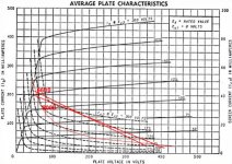
One can also obtain screen drive plate curves from most sweep tube data sheets, measured with G1=0 volts, from which G2 transconductance may be determined, or G2 drive load lined directly plotted (see attachment).
If you drive both G1 and G2 together, the net gm can be calculated in a manner similar to calculating resistances in parallel, using the G1/G2 drive voltage ratio.
Attachments
I have built prototypes (and tested) with this principle by using the tubes 811A, GU50 and 807.
How did you find the operating points? Limiting factor in trying some of these designs seems to be want of data for those without curve tracing capability.
Thanks!
How did you find the operating points? Limiting factor in trying some of these designs seems to be want of data for those without curve tracing capability.
I begun with 811A. Its datas are well available. I searched for optimum bias and anode voltage that suited my Edcor GXSE15-8-10 k and GXSE15-6-10k transformers (10 k to 6 ohms and 8 ohms ).
Then is continued similarly with 807 and GU50 by experimentation.
I use adjustable power supplies and distortion analyser together to find the best operating conditions.
Hi Lechuck
I want to build it. What are the voltages you are using? Do you have recommendations for the power supply and transformers? Thanks very much.
Very good! I do have some suggestions based upon the orignal Synola schematics.
Firstly I don't like the ECC82 buffer stage. I have tried to replace it with a double 6CG7, however this tube is not able to provide both the current for R5 and for the screen of the power tube. Removing R6, putting an EL84 in place of the 6CG7 and changing R5 to 6.8k - 20W seems to be the solution. This removes all the ugly distortion that you'll get when the screen grid of the end tube is not correctly driven by the buffer stage.
I have tought myself SPICE last weekend to play around with the schematics. I found out that there is no real reason for the buffer stage to be grounded. In my schematics R5 draws almost a wimpy 30mA and consumes 7.5W, the screen grid draws about 8-15 mA. This means that the buffer needs to provide 38mA at zero signal and at least 45mA at max. I realized that R5 can be removed because the screen grid of the power tube consumes enough current to keep the buffer going. The buffer stage now only consumes the current that the screen grid draws, and we save about 20 watts of unused energy.
I think that a single ECC82 triode could be capable to provide the current needed for the screen grid, thus you can use two JJ ECC832 tubes to reduse the amount of tubes. Simulations confirm this, however I still have try this in the real world.
The power supply that I am currently using allows me to parallel the end tubes and gives me a B+ of 360 volts. My OPTs are 2.5k primairy.
So in short, drop R5, R6 and one ECC82. Then connect the cathode of the remaining ECC82 directly to the screen grid of the power tube.
Feel free to drop me a PM.
Last edited:
I think that it would be useful to test a higer gm driver (ECC88...6N6P, 6J9P (E180F) etc. etc). The problem with ECC82 is its low gm and thus too high output impedance.
Have you notice that the buffer does not need to be grounded by simulation or in practice too ?
When the cathode resistor of the buffer stage is removed, the total current is reduced, but also the transconductance of the buffer, which is fatal to the linearity of the buffer stage.
Have you notice that the buffer does not need to be grounded by simulation or in practice too ?
When the cathode resistor of the buffer stage is removed, the total current is reduced, but also the transconductance of the buffer, which is fatal to the linearity of the buffer stage.
I think that it would be useful to test a higer gm driver (ECC88...6N6P, 6J9P (E180F) etc. etc). The problem with ECC82 is its low gm and thus too high output impedance.
Have you notice that the buffer does not need to be grounded by simulation or in practice too ?
When the cathode resistor of the buffer stage is removed, the total current is reduced, but also the transconductance of the buffer, which is fatal to the linearity of the buffer stage.
I didi try this yesterday with the EL84 buffer stage, it seems to work very well. I still have to hook up my scope to see how it performs, but for now my ears tell me its good
- Status
- This old topic is closed. If you want to reopen this topic, contact a moderator using the "Report Post" button.
- Home
- Amplifiers
- Tubes / Valves
- EL509 (JJ) or PL519?