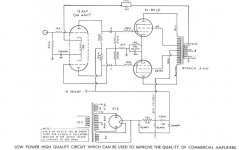
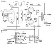
Hello all you experts. I'm new here and have just finished a Dynaco A-140 6BQ5 push/pull dual channel amp. I made some mods to the original to account for the parts I had on hand. I've indicated the voltages I get on the amp while it's in operation. It sounds pretty good to me, I just want to know if it will burn up or worst because of the changes I made to the power supply and wired it for stereo. I'm using 6P14P in leu of 6BQ5's.
Thanks for any advice or criticism.
Thanks for any advice or criticism.
Attachments
Hi Bruce,
Nice amp! I have Mono Eico HF-12's which use 6CA4 rect. tube. It may be overloaded with 2 channels as Stereo Integrated HF-81 & Power amp HF-86 uses 2 of these tubes. You may copy that PS. Also you might switch the 47 mfd cap with the 33 mfd as 20-30 mfd is proper for that rect. tube. If you put IN4007 or better yet UF4007 in series with PS trans output and the 1 and 7 pins of your rectifier tube you might take most of the load off of it and help bass. 5AR4 would work but you should still switch caps. I read Two 6CA4 will give better bass than one big rect. tube.
Hope that helps!
Randy
Thank you for the advice. Is this how I should modify the power supply?
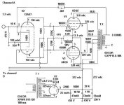
I would like to ask you about the cathode resistor (150R 5watt). I have all four cathodes tied together (pin 3) and only 1 resistor for all four tubes.
There is a 12.1 volt drop across this resistor, so approximately 80 ma is flowing thru it, and each tube is then drawing 20 ma does that sound correct to you?
I very much appreciate you time, thank you.
Attachments
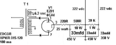
I'm sure the diodes should help that overloaded tube. You still may want to copy HF-81 schematic with 2 6CA4 for best reliability and sonics. For a super solid PS get another transformer and monoblock it. I think you can use your 47 cap as the second one if you wish.
Your talking about the output tube cathode bias I presume. In diytube.com there is an interesting article in the ST35 Dynaco amp form on that. It in a thread in improving the performance of the SCA35 Dynaco Integrated amp. The author Dave Gillespie develped a fixed bias setup using a negative voltage regulator.
http://www.tronola.com/A_New_Look_At_An_Old_Friend_Rev0.pdf
Read the thread in diytube.com for more info too!
Might be well worth doing as it improves tube life and sonics as explained. He mentions the negatives of cathode bias and especially one cap and resistor Dynaco used to bias all 4 tubes. I've got to try it on my old HF-12 and Heathkit AA-151.
It is recommended if in other forms I read to go to the resistor and cap to each pair of output tubes if you want to keep that system. Look at the EICO HF-81 schematic.
They are easy to find for free. PDF Manual's for Eico HF-12 and HF-81 have the best quality schem. I tried to up load them , but much too big.
Good luck,
Randy

Bruce --
Your output tubes are running much too cold to produce the power these tubes are capable of using cathode bias. To run them at the proper current levels will either require an additional rectifier tube, or a single bigger tube. Also, the added resistance you have in the power supply to achieve your target B+ level is a concern as well. As the output stages draw more current, the voltage will drop significantly across these resistors. Do you know what the screen % is for your OPTs? This will play significantly into what type of bias scheme is best for your amplifier.Finally, lowering the value of the upper grid return resistor slightly will help balance the phase inverter stage better.
I am right up the road from you over in the Braselton area. If you'd like, we can put your amp on the bench in the lab and see what it's really doing. PM me if you're interesterd.
Randy -- Thanks for the link to my article!
Dave
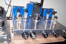
Hi Bruce -- You have a very nice looking amp there! Congrats on a very nice looking build.
The bias for your output stage looks much better now, with a more typical operating point for the tubes that will allow them to produce rated power with minimum distortion. The reduced resistance in the power supply will also aid in increasing power, minimizing distortion, and overall, allowing the amplifier to sound much more dynamic.
If the amplifier is constructed the way you show the FB network connected into the cathode circuit of the 12AX7, then there is actually no FB at all, as the capacitor connected between the 12AX7 cathodes and ground would short out any FB presented there. Is it possible that the schematic is simply misdrawn? The usual way such circuits are configured would have the cap and 1K resistor both connected between the "bottom" 12AX7 cathode and ground, the 270R resistor connected between the top and bottom cathodes, and the FB inserted into the top cathode. That would make much more sense, allowing the FB signal to be developed across the 270R resistor.
Also, is the intention of the control in the FB network to be a tone control of sorts? Assuming that the schematic is misdrawn as noted above (so that FB is actually being applied), the network is still providing little feedback when the control is set for maximum FB. If this control is a tone control, while feedback tone controls are almost always better than passive controls, inserting them into the feedback loop of the power amplifier is usually a poor way to go. Tone control should be accomplished in any preamplifier circuitry ahead of the power amplifier proper.
To really get the FB loop right requires a scope and testing with square waves at a minimum. A proper FB loop can make or break the performance of an amplifier, as a good loop will lower output impedance and distortion while raising frequency response, where as a poor one will either not function at all, or cause such instabilities as to ruin performance and possibly even speakers in the process. None of this is meant to scare you off from applying FB to the design. It's just one of those things that when it's good, it produces many benefits, but when it's bad, it causes just as many problems.
Other than the concerns noted, your design is coming along quite nicely. I have no doubt it has the capability of being a very fine performing amplifier. The basic topology used has endeared the sound of tube amplifiers to a generation. Good luck with your project!
Dave
- Status
- This old topic is closed. If you want to reopen this topic, contact a moderator using the "Report Post" button.
- Home
- Amplifiers
- Tubes / Valves
- Rate/critique my Dynaco A410 mods..