So if we produce a 1Khz 0db sine, what would the harmonic content be with an amp that has .5% HD?
What would the levels of those harmonic frequencies be?
Would a speaker produce a different set of harmonics of a recorded tuning fork compared to a live tuning fork, played through an amp with .5% HD?
A (ideal) tuning fork produces a sine wave. No harmonics at all, so after being recorded and played back through an amp and speaker it will have some added harmonic content. Sources that start out with some harmonic content also have added harmonic content when recorded and played back.
.5% THD can be composed of any number of components at any ratios that add up to .5% of the input signal. Which shows why THD is not enough information. 0.5% of 2nd harmonic will sound way different from 0.5% of 9th harmonic, but both will result in the same amp specification of 0.5% THD.
Running the 807 in triode mode with 5K reflected at 8 ohms will provide a decent damping factor and will probably sound great. As atmasphere says, therer is a lot more to the story than the impedance curve.
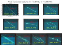
For example, here's what a load line looks like playing music into a speaker. The H axis is plate voltage and the V axis is plate current. This is a triode amp playing on a 3 way box speaker showing various plate load line resistances superimposed, with some sine tones for reference.
Notice that as the plate load impedance goes from 10K to 20K ohms at a speaker peak, the plate voltage swing (horizontal axis) doesn't increase very much. An undamped pentode may behave differently, but here we're talking about triode mode.
Cheers,
Michael
PS What I want to know is; with enough distortion, can you play stairway to heaven on a tuning fork?
Attachments
Last edited:
Why pick 5th, 7th, 9th? Negative feedback around a non-perfect amplifier produces all orders, odd and even, but if enough is used these can be small. Note 'enough' - 'some' can be worse than 'none', but that does not necessarily mean that 'none' is always best. It depends how linear the amp is to start with.
A (ideal) tuning fork produces a sine wave. No harmonics at all, so after being recorded and played back through an amp and speaker it will have some added harmonic content. Sources that start out with some harmonic content also have added harmonic content when recorded and played back.
.5% THD can be composed of any number of components at any ratios that add up to .5% of the input signal. Which shows why THD is not enough information. 0.5% of 2nd harmonic will sound way different from 0.5% of 9th harmonic, but both will result in the same amp specification of 0.5% THD.
Running the 807 in triode mode with 5K reflected at 8 ohms will provide a decent damping factor and will probably sound great. As atmasphere says, therer is a lot more to the story than the impedance curve.
For example, here's what a load line looks like playing music into a speaker. The H axis is plate voltage and the V axis is plate current. This is a triode amp playing on a 3 way box speaker showing various plate load line resistances superimposed, with some sine tones for reference.
Notice that as the plate load impedance goes from 10K to 20K ohms at a speaker peak, the plate voltage swing (horizontal axis) doesn't increase very much. An undamped pentode may behave differently, but here we're talking about triode mode.
Cheers,
Michael
PS What I want to know is; with enough distortion, can you play stairway to heaven on a tuning fork?

Heeeheee! Great post!
About %HD, if we had a 1khz 0 db sine and ONLY 2nd harmonic at .5% would that be equal to 1/200 of the 0db level? If it was a 1v signal, is .5% equal to a .05v harmonic signal?
So if we produce a 1Khz 0db sine, what would the harmonic content be with an amp that has .5% HD?
What would the levels of those harmonic frequencies be?
Very slight- usually buried in the noise of most distortion analyzers (which always makes me question why I still keep one on the shelf....) 100ths of a percent is audible. Compare that to our sensitivity to lower orders where we have almost no sensitivity at all! Actually, we do hear that too, only it gets described as 'warmth', 'body', 'tone', 'harmonic density', 'bloom', etc.
Would a speaker produce a different set of harmonics of a recorded tuning fork compared to a live tuning fork, played through an amp with .5% HD?
What do you mean by different? other than those mentioned? Of course I am sure we both know that speakers make HD of their own. Its always amazed me though that most speakers do allow one to hear very small changes in odd-ordered harmonic content in amplifiers like we are discussing here.
Thanks everyone for the excellent information! I am glad to hear that there has been success with SE tetrode amps coupled with some Klipsch.
Michael, those pictures are great! It's very interesting to see just how much the loadline changes as the frequency changes.
Another interesting point to note is that apparently, our ears are more sensitive than some distortion analyzers. This of course results in the argument of objective vs. subjective testing.
I figure I'll try the amp with no feedback, and if it just doesn't sound right, I'll play around with feedback. I have a 'scope and a frequency generator, so tweaking some feedback shouldn't be terribly difficult. However, it'll be a month or so before I get my iron from Edcor.
Kyle
Clipping has nothing to do with negative feedback, although negative feedback can cause the onset of clipping to be more severe. Clipping is created by distortion as the output devices saturate, which has little to do with feedback.
I see clipping has something to do with NFB. Especially with difficult load such as a real loudspeaker is. Imagine a non-NFB pentode output stage with relatively high output impedance, say 100 ohms, is connected to the speaker having the impedance curve like this:
An externally hosted image should be here but it was not working when we last tested it.
At the bass resonant frequency the impedance of the speaker is some 70 ohms while the nominal impedance is 10 ohms.
Now at bass resonant frequency the output voltage of the amplifier will rise some 12 dB compared to 1 kHz due to the high load impedance of the speaker. This big voltage rise can obviously cause clipping even at relatively small output levels.
However, if this amplifier was be equipped with such amount of NFB that the output impedance will drop to 10 ohms, the voltage rise will be only some 4,5 dB and the amplifier is not that "sensitive" to clipping.
I see clipping has something to do with NFB. Especially with difficult load such as a real loudspeaker is. Imagine a non-NFB pentode output stage with relatively high output impedance, say 100 ohms,
At the bass resonant frequency the impedance of the speaker is some 70 ohms while the nominal impedance is 10 ohms.
Now at bass resonant frequency the output voltage of the amplifier will rise some 12 dB compared to 1 kHz due to the high load impedance of the speaker. This big voltage rise can obviously cause clipping even at relatively small output levels.
I can tell you've not actually played with tubes a whole lot to make a statement like that.
First, to assume a power amp with a 100-ohm output impedance is ... absurd. But for the sake of this model, you would find that the peak in impedance would be the area where clipping is *least* likely to occur, not the most! An amplifier with a 100 ohm output impedance will be much more challenged by the 10 ohm load that it will 70 ohms.
It is important to also understand that while global negative feedback can *seem* to reduce output impedance, it will do nothing at all to increase power with lower impedance loads, something that really is the defining attribute of an amplifier with a low output impedance. What feedback does is impose a servo control on the amplifier, not somehow cause the ability of an amplifier to suddenly manifest more power.
IOW if a tube amp is capable of 10 watts into 4 ohms before clipping, no amount of feedback is going to increase that power. In order to do that, you might have to add more power tubes, or a larger tube, or increase the B+ voltage (without frying the tube), stuff like that.
Okay, great. I first have to get the amp built, and then get some tweeter diaphragms for the K-77s.
Thanks!
Kyle
Your new K-77 coils will thank you for using a tube amp from now on. Make sure you clean all the old burnt varnish from the gap before installing the new ones. Sometimes you have to unwind the wire out of the gap it's stuck so badly (Curly sez "no wonder it don't woik; it'a all fulla wires!").
I like replacing the entire assembly as opposed to having to mount the bare diaphragm. Looks like "pascalite"...
Klipsch part # 127126 K-77-F Diaphragm kit; also called the T-35 repair kit.
I can tell you've not actually played with tubes a whole lot to make a statement like that.
It seems you have and also use crystal ball as a tool
.First, to assume a power amp with a 100-ohm output impedance is ... absurd.
Here is a small homework to you:
Please let us know the output impedance of a typical EL84 pentode connected SE-output amplifier having 4,5k to 8 ohms output transformer
(...and with typical Ua and Ug2 value 250 V).
But for the sake of this model, you would find that the peak in impedance would be the area where clipping is *least* likely to occur, not the most!
I think I have not said that bass resonant frequency is most prone frequency to clipping. The reason for clipping is impedance peak.
The phenomenon is same what ever the frequency of the impedance peak is.
An amplifier with a 100 ohm output impedance will be much more challenged by the 10 ohm load that it will 70 ohms.
Please give more detailed explanation and some arguments.
It is important to also understand that while global negative feedback can *seem* to reduce output impedance, it will do nothing at all to increase power with lower impedance loads, something that really is the defining attribute of an amplifier with a low output impedance.
You are unfortunately wrong.
Assume you have an amplifier with small or no NFB and having an output impedance of 8 ohms. It is connected to 8 ohms load and is adjusted to, say 8 volts across this load ( 8 W ). If now the load resistance is halved to 4 ohms, the voltage across load will obviously drop to 5,33 V representing some 7,1 watts.
Then you add NFB so that the output impedance of the amplifier will drop to 4 ohms. What happens ?
Let's connect it again to 8 ohms load and adjust the output voltage to 8 volts. Then we connect the 4 ohms load instead and see that the output voltage drops to 6 V representing 9 watts.
All this obviously provided that the amplifier is well in it's operating region, not fully loaded.
I think I have not said that bass resonant frequency is most prone frequency to clipping. The reason for clipping is impedance peak.
The phenomenon is same what ever the frequency of the impedance peak is.
I can see that you have not actually tried this. The peak of impedance will be the arena of least clipping, assuming the prior model of amplifier with 100-ohm output impedance. IOW, given a load as previously presented, as frequency is varied to explore the range on the chart, the clipping onset will be found to occur at a much reduced power and voltage output into the low impedances as opposed to the high impedances shown.
Tube circuits that lack feedback often approach current sources in their behavior and consequently prefer higher impedances if output power is your goal. They have a power transfer characteristic, that if graphed, looks a lot like the side view of an air foil of an aircraft. There will be a peak in output power that will have correspondence to the output impedance (depending on what means is used to measure that, there are several different methods that yield different numbers).
If the load is less than that of the amplifier output impedance, most of the power generated will be dissipated in the output section rather than the load. There will also be found to be a maximum impedance beyond which the output power of the amplifier will begin to fall off, but more gently than it will if the load is less than the output impedance. This gives the power transfer curve the airfoil appearance.
Assume you have an amplifier with small or no NFB and having an output impedance of 8 ohms. It is connected to 8 ohms load and is adjusted to, say 8 volts across this load ( 8 W ). If now the load resistance is halved to 4 ohms, the voltage across load will obviously drop to 5,33 V representing some 7,1 watts.
Then you add NFB so that the output impedance of the amplifier will drop to 4 ohms. What happens ?
Let's connect it again to 8 ohms load and adjust the output voltage to 8 volts. Then we connect the 4 ohms load instead and see that the output voltage drops to 6 V representing 9 watts.
All this obviously provided that the amplifier is well in it's operating region, not fully loaded.
The only problem here is its not the same argument. We are talking about onset of clipping, not the behavior of an amplifier that has some headroom to play with.
If you were to use a transistor amplifier in the model above, I would be inclined to agree, but with tubes you have the matter of the OPT and the tube being a pentode or triode (either of which is at saturation), and so you cannot generalize in this fashion. You also have the problem of Kirchoff's law, which really won't let you get more power for nothing. In essence so far your argument has seemed to be that if you add feedback, you get more power. Power takes more power supply, more tubes, bigger OPTs and the like, its not the sort of thing that appears simply because you fed some output signal voltage back to mix with the input.
I see clipping has something to do with NFB. Especially with difficult load such as a real loudspeaker is. Imagine a non-NFB pentode output stage with relatively high output impedance, say 100 ohms, is connected to the speaker having the impedance curve like this:
An externally hosted image should be here but it was not working when we last tested it.
At the bass resonant frequency the impedance of the speaker is some 70 ohms while the nominal impedance is 10 ohms.
Now at bass resonant frequency the output voltage of the amplifier will rise some 12 dB compared to 1 kHz due to the high load impedance of the speaker. This big voltage rise can obviously cause clipping even at relatively small output levels.
However, if this amplifier was be equipped with such amount of NFB that the output impedance will drop to 10 ohms, the voltage rise will be only some 4,5 dB and the amplifier is not that "sensitive" to clipping.
The horrible sound you might hear when that speaker hit the resonant frequency is not the amp clipping, it's the driver beating itself to death.
Sheldon
- Status
- This old topic is closed. If you want to reopen this topic, contact a moderator using the "Report Post" button.
- Home
- Amplifiers
- Tubes / Valves
- SE Amps with Variable Impedance Loads