Hi,
Newbie alert:
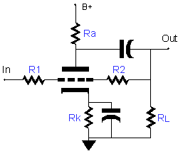
I am planning on designing a anode follower as an output stage to my tda1541 dac. I was planning to use this topology, but was wondering about the purpose of R2, and how to calculate appropriate values. Is it a simple grid leak?
Morgan Jones does really describe the anode follower (don't know why), so any help is appreciated.
Thanks
Newbie alert:
I am planning on designing a anode follower as an output stage to my tda1541 dac. I was planning to use this topology, but was wondering about the purpose of R2, and how to calculate appropriate values. Is it a simple grid leak?
Morgan Jones does really describe the anode follower (don't know why), so any help is appreciated.
Thanks
R2 is there to provide negative feedback - good explanation here
Designing Single-Stage Inverting Feedback Amplifier
Designing Single-Stage Inverting Feedback Amplifier
R2 is the feedback resistor. To a first approximation, voltage gain = -R2/R1 (like the inverting op-amp). In that circuit it is also arranged to be part of the grid leak via RL, but you could do it differently if you wanted.
R1 sets the input impedance - generally as low as possible for most current-output DACs. You could even try omitting R1, then you have a transimpedance stage (current in, voltage out). Input impedance would then be roughly R2/mu - which could still be too high for the DAC chip. Many circuits seem to get away with violating the DAC data sheet requirements - whether this is because DACs are more tolerant than their makers suggest, or people who fiddle with DACs are more tolerant of distortion than they realise I am not qualified to judge.
R1 sets the input impedance - generally as low as possible for most current-output DACs. You could even try omitting R1, then you have a transimpedance stage (current in, voltage out). Input impedance would then be roughly R2/mu - which could still be too high for the DAC chip. Many circuits seem to get away with violating the DAC data sheet requirements - whether this is because DACs are more tolerant than their makers suggest, or people who fiddle with DACs are more tolerant of distortion than they realise I am not qualified to judge.
R2 is the feedback resistor wich sets the gain as being roughly (R1 + R2) / R1 providing that the gain you need is lower (says 1/20) than the Mu of the triode.
Output and input impedances decrease as much as this ratio is high so, without R1 (understand 0 ohms) the input impedance fall down and it's probably what your TDA1541 expects for good linearity.
Yves.
Output and input impedances decrease as much as this ratio is high so, without R1 (understand 0 ohms) the input impedance fall down and it's probably what your TDA1541 expects for good linearity.
Yves.

Allright, so I have done the math, but not sure of some things.

1. The value of R2 seems very high, and does not fit with your role of thump R1/R2=gain. I have calculated it using the formula on the aikenamps website (Rf = ( ((Ri+Ra-(Ri*A))*Acl)-Ra ) / (A-Acl).
I will use 2 parallel tda1541, so i/v converter of 28R is appropriate. That means I will be looking for A=12.4=Vout/Vin to get to 2Vpp on the output.
2. I was wondering about the 2mA 'DC' offset that the tda produces. In this setup, will that be present on the output? as there is no cap to block dc coming from the grid.
BTW the 6n16 datasheet is here
Thanks for the help!!
Last edited:
One additional question. According to my calculations, the output cap needs to be 18uF... this seems extremely high (with according price tag etc). Increasing the cutoff frequency from 1 to 2Hz halves the required output cap. Are there significant audible differences if I pull the cutoff frequency up ?
I did say approximately! For the normal situation where the open-loop gain is much higher than closed-loop gain, and the resistors are reasonably high in value.
Your amp is basically a transimpedance amp. R1 is not doing very much, as the input impedance is dominated by the feedback (roughly R2/(mu-1) , I think?). To a first approximation, output voltage = input current x R2. This is for AC.
For DC the input current sees primarily the 1M to ground. Not good! A DAC chip needs to see a low DC resistance as well as low AC resistance. You need to think about that as well. To make things more complicated, many DACs need to see a low resistance not to ground but to some slightly higher voltage. This is easily provided using an op-amp virtual earth, but more diffcult with a valve.
The output capacitor need not be that big. You can't hear 2Hz. Your loudspeakers can't reproduce it. No CD will have any signal that low, even reggae or organ pedals stop a bit higher up. You are unlikely to hear any difference until the roll-off gets to above 10-20Hz. With small speakers even higher is possible.
Well, I was going to say that you seem to be attempting something beyond your current understanding, but I didn't want to appear rude. I think your best bet is to look at what other people have done, and try to understand exactly how each one works. The basic idea of an anode follower is fine - it is one way of doing it with valves. Remember that you have to provide a low impedance for the DAC to see from DC up to beyond the audio range, but you don't necessarily have to provide all this in the same way. Some people just use a small resistor to ground (or the reference voltage) then use a capacitor-coupled valve stage. That is probably the simplest method; it is essentially passive I/V followed by an amp.
Others have used grounded-grid, but that may have its own problems. Some use a transformer. Bear in mind that some DIY circuits may violate the chip data sheet requirements but people seem to get away with this (or maybe their hearing is not quite as good as they imagine!).
Others have used grounded-grid, but that may have its own problems. Some use a transformer. Bear in mind that some DIY circuits may violate the chip data sheet requirements but people seem to get away with this (or maybe their hearing is not quite as good as they imagine!).
- Status
- This old topic is closed. If you want to reopen this topic, contact a moderator using the "Report Post" button.
- Home
- Amplifiers
- Tubes / Valves
- Function of R2