The "high end" practice of selling scrapless EI lams with silver windings is beyond belief to me, like selling quitar amplifier OTs with gold cases.
In case of audio output transformer silver wired secondary does make a sense for one very obvious reason - it allows to use wire with smaller diameter. Winding of audio trafo requires a lot of space, and "standard" cores/bobbins are often not so good for them. Either you have to sacrifice secondary DC resistance, either choose bigger core (which is more heavy and occupies too much real estate on chassis). Its not always, but often.
As for the impact of silver wire to sonic properties, I have not seen any sound scientific/engineering evidence in any reputable publication except some marketing crapolla made for purpose of profit.
"Hmmm, I did not get your point entirely. Audio transformer primary have several thousands of primary turns, so even each half of primary (plate end <-> center tap / center tap <-> plate end) will occupy several layers."
The "progressive wind" technique I mentioned above will do a multi thousand turn winding in just one "layer". It uses a back and forth oscillation of the core during winding (dithering summed with the slow continuous forward rotation) so that the turns stack up in chevron shaped mini "layers" at an angle to the core, this keeps distributed capacitance to a minimum by keeping similar voltage turns localized in the winding. You need a fancy uP controlled toroid winder for this. It does still need adequate dielectric between the separate windings to avoid interwinding capacitance problems. You also need a core with a larger than usual inside window diameter for progressive winding. Like current transformer cores.
The isolated GE Variac I mentioned above used just single layer depth progressive winding, ie, a core and wire size such that only a single wire depth progressive layer achieved sufficient turns for the line voltage. It had a rather thick molded plastic dual cupped sleeve arrangement (two pieces, one from top and bottom fitted) that fit over the inner winding, with ridges on the outside to position the outer Variac winding firmly for the brush wiper.
Stacked multiple "single" layers would require inordinate amounts of interlayer dielectric tape to keep the distributed capacitance down to reasonable levels. Which would increase the leakage L due to the many winding gaps.
And then there are the "random wound" toroid windings. Well, I haven't seen any workable audio OTs using that scheme. Most of the 60/50 HZ line voltage power toroids are wound that way, since the huge distributed capacitance is actually a benefit there for neutralizing the primary inductance. (power factor)
Last edited:
Is there a standard frequency at which the impedance of an audio output transformers primary winding is stated? I have a Hammond output transformer whose primary winding measures 3.3k @ 100cps, 20k @ 1000cps and 40k @ 10000cps.
I'm not sure there is a standard, though, if there is one I'd think 1 kHz would be used.
You need to measure the loaded impedance, though. I.e. load the secondary with the rated speaker impedance and measure the impedance "seen" at the primary. The magnitude of this impedance should be the rated primary impedance for the transformer.
I've measured a couple of Edcor XSE and CXSE transformers using an HP 4194A impedance analyzer. As I recall, the measurements showed the magnitude of the impedance being fairly flat across the audio band. I used an 8-ohm resistor as the load on the secondary.
~Tom
Duh ?In case of audio output transformer silver wired secondary does make a sense for one very obvious reason - it allows to use wire with smaller diameter.
Resistivity of silver is -only- the 16/17th of copper

Résistivité - Wikipédia
Yves.
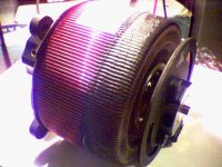
A big window core from a current xfmr, suitable for a high turns progressive wind OT.
The core pictured has really big window, but too small cross-section (as I can judge by appearance).
The "progressive wind" technique I mentioned above will do a multi thousand turn winding in just one "layer". It uses a back and forth oscillation of the core during winding (dithering summed with the slow continuous forward rotation) so that the turns stack up in chevron shaped mini "layers" at an angle to the core, this keeps distributed capacitance to a minimum by keeping similar voltage turns localized in the winding. You need a fancy uP controlled toroid winder for this. It does still need adequate dielectric between the separate windings to avoid interwinding capacitance problems. You also need a core with a larger than usual inside window diameter for progressive winding. Like current transformer cores.
Stacked multiple "single" layers would require inordinate amounts of interlayer dielectric tape to keep the distributed capacitance down to reasonable levels. Which would increase the leakage L due to the many winding gaps.
And then there are the "random wound" toroid windings. Well, I haven't seen any workable audio OTs using that scheme. Most of the 60/50 HZ line voltage power toroids are wound that way, since the huge distributed capacitance is actually a benefit there for neutralizing the primary inductance. (power factor)
Random wound audio toroids would be a total crap indeed. BTW, winding audio toroid don't need progressive winding. Number of secondary layers is determined not only by winding layout scheme, but also by target secondary resistance, which should be less then 0.5 Ohm on 8-ohm output tap. Wound with the progressive winding technique, secondary will have only 2 layers connected in parallel, and require enormously thick wire. Technically it is not a problem to put wire with diameter up to 2.5 mm, but it is not likely to be accurate.
Well designed audio toroid (50W - 100W / 3 - 5K) with properly interleaved primary/secondary, both 4 and 8 Ohm output taps, will have leakage inductance less then 20mH .
Rule of thumb : void wire larger than 0.8mm to reduce skin effect or go multifilar . . .. . .
Technically it is not a problem to put wire with diameter up to 2.5 mm, but it is not likely to be accurate.
Looks four fold too hiWell designed audio toroid (50W - 100W / 3 - 5K) with properly interleaved primary/secondary, both 4 and 8 Ohm output taps, will have leakage inductance less then 20mH .

Hi, Peter! Have you sourced GOSS Hi-B double C cores?
Yes, they came by boat
Looks four fold too hi
Nope, for transformer of that size and number of turns it is normal, proofed by both theory and practice. BTW, 15 - 20 MH for big 5K transformer is very good value.
How can I measure the inductance at 20Hz?Usually primary inductance is measured at 100Hz/1V, since most LCR meters use fixed voltage - 1V, and 2 fixed frequencies - 100 Hz and 1 KHz.
Or calculate it from the measured 1Khz data?
Tyimo
How can I measure the inductance at 20Hz?
Maybe with one of the older analogue inductance bridges.
But then does it make you any wiser?
The inductance is there to have enough low frequency bandwidth, and to prevent the core from saturation.
For grain oriented silicon steel the inductance varies with frequency and signal level.
The best way to check if the transformer is up to it's duty is to measure the output stage of the tube amp with a signal generator and see at what frequency and output power the wavevorm starts to distort. You will see that for instance you will have 6 watts of undistorted power at 30 Hz, and 4 watts at 20 Hz. That gives more insight in the quality of the output transformer than a low signal static measurement by some inductance meter.
yes, but I still would like to know it!The best way to check if the transformer is up to it's duty is to measure the output stage of the tube amp with a signal generator and see at what frequency and output power the wavevorm starts to distort.
How can I measure the inductance at 20Hz?
Or calculate it from the measured 1Khz data?
Tyimo
You can do it with professional L-meter. Or use permeability curves to calculate it.
See why I mainly build OTLs? Just kidding. I have some fine OT amps as well and I can't wait till I get to try a 'higher end' OT than the cheap Edcors. I must say tho, as good as the amp sounds with Edcors, I wonder how much better a mega dollar OT will make it sound. I need a pay rase.
Push-pull amplifiers with low Rp may have very big disadvantage - high sensitivity to phase shift caused by leakage inductance, and as result, oscillation.
In the books I have it is noted that for high Rp tubes (>=3.6K) maximal recommended value of leakage inductance is 20 mH, for low Rp tubes - 7 mH. Indeed, it is not so easy to obtain, especially with EI core.
Additionally, transformers with large core and small number of primary turns may have suboptimal performance on low signal level.
BTW, 40H for 5K transformer is a way too low. Small discrepancy of output tubes idle current (which is always there) will magnetize core and drop inductance. There are not so many ways to cure this. Lundahl, for example, uses micro air gap.
Interesting. Will this still apply in an amp without loop NFB? I haven't built any PP OT amps with the 6AS7 yet, and will keep this in mind. (Tho to be honest I find it hard to believe this is much of a problem, since I've not heard of such problems from other similar projects)
- Status
- This old topic is closed. If you want to reopen this topic, contact a moderator using the "Report Post" button.
- Home
- Amplifiers
- Tubes / Valves
- Output Audio Transformer Impedance