The FFT above was taken with a GE jan12b4a NOS with a Gyrator load. The B+ is supplied by a SSHVS with incoming voltage of 300V and total current of 63mA
B+ =210V
Anode = 130V
Vb = 15.2 V with a series of 8 LED bypassed with 660uF FC type electrolytics
I have not yet bypassed the electrolytics with a good film.
Tube Bias is 19.9mA
Input impedance was 100k with no attenuation in circuit.
Filaments are DC 6.3volts regulated and then biased to 20Volts above ground.
Input signal was 0.1667 Vrms Sine from soundcard
Output was 1.0 Vrms
Measurements were taken direct to 1616m Soundcard.
The soundcard was brought close to test stand and short (20cm) RG59/U cables were used.
The FFT shown above has been verified at three different test sessions. The frequency response is 10Hz-40,000Hz +/- 0.02dB. 40,000Hz is useful limit of the testing parameters of 96k/32bit.
Hope that answers the particulars......
I am working on a report where I tested the gyrator loaded 12b4a set-up from 120V to 180V and at various biases looking at S/N, THD, and frequency respose. It is going to take a while as there is alot of data collected and would like to have it peer reviewed before I post it in a blog.
Hello SGregory,
I realize the danger, I was just thinking.
The output of the soundcard may interact with the impedance of the attenuator. Have you considered removing the attenuator from the test bed and adjusting the voltage out of the soundcard in the mixer software?
DT
All just for fun!
I realize the danger, I was just thinking.
The output of the soundcard may interact with the impedance of the attenuator. Have you considered removing the attenuator from the test bed and adjusting the voltage out of the soundcard in the mixer software?
DT
All just for fun!
That is how I do it now. For the 12b4 I set the output of the card to 0.167 Vrms to get 1.0Vrms output on the DUT. I still have the attenuator in but for testing, its purpose is only to set the input impedance.
I decided to leave the stepped attenuator in so that at some point I can take it to my system and listen to it. I am waiting on a new PT from Jack before I can move it. The Kepco 400B has a very low WAF in the living room!
Today measureing IMD.
I decided to leave the stepped attenuator in so that at some point I can take it to my system and listen to it. I am waiting on a new PT from Jack before I can move it. The Kepco 400B has a very low WAF in the living room!
Today measureing IMD.
Hello SGregory,
That Kepco 400B looks like a beast. I am sure that it has a good home on your bench. I have bought output transformers from Electra-Print Jack, they serve well. I have had good results with Allied and Edcor power transformers.
For your new 12B4A power supply are you using the Salas HV shunt?
DT
All just for fun!
DT,
Yes the Salas Simplistic High Voltage Shunt (SSHVSR) will be used.
The power supply will be a CLC type putting out 300V. Probably a little hot on the SSHVSR but I have enough heat sink.
I have Allied and Edcor PT's and I agree they work well. The problem was I wanted a 12.6Vct filament winding for the DC filament regulator and could not find a standard one to fit the application. Knowing what I know now with operating point for the 12b4 tube I could have gotten away with a couple of the edcors and had a cooler voltage.
I should point out that the SSHVSR makes a huge difference in PSRR obviously. I'll post some data shortly comparing a resistive loaded 12b4 with and without the SSHVSR.
Last edited:
Today I wanted to compare the performance of the Gyrator vs a resistive anode load on the 12b4. That expanded to look at the impact of the SSHVSR. So I will start with the SSHVSR first.
Conditions 1Vrms=0dB 6kResistor Anode Load. Using the same operating point described earlier with the anode = 130V etc.
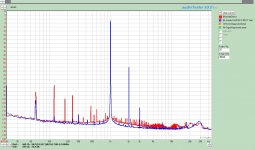
The main impact of the SSHVSR was in noise. As can be seen in the first plot, not only does the SSHVSR reduce drastically 60Hz and its harmonics , but the general noise floor as well.
Red = No SSHVSR Blue= With SSHVSR
There was no significant difference in THD with or without the SSHVSR although it did provide for a better S/N ratio by 4dB. THD measured 0.122%.
So the SSHVSR stays at this point.
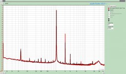
Bringing the Gyrator in is were we start to see some significant differences in the harmonic performance. In the second FFT plot we see that comparison. In both cases the SSHVSR is employed and tube operating point is the same. The second harmonics have dropped by 20dB while the third has remained the same. Although not really a huge difference but I consistantly saw a couple of dB greater noise floor with the gyrator above 3kHz compared to the resistive load. However, at less than -135dB I am not going to complaign.
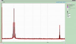
Finally, I looked at the IMD between the two. The third plot attached shows a 70Hz/6000Hz signal at 4:1 amplitude ratio for both the resitive load and Gyrator. The Gyrator exhibits a lower 2nd order band and a slightly higher 3rd order band. Total IMD is improved however with the gyrator. I need to find my MJ book to calculate the number for the IMD Distortion.
The frequency response for both configurations was flat from 10Hz-40kHz
Hope you find this as interesting as I did.
Conditions 1Vrms=0dB 6kResistor Anode Load. Using the same operating point described earlier with the anode = 130V etc.
The main impact of the SSHVSR was in noise. As can be seen in the first plot, not only does the SSHVSR reduce drastically 60Hz and its harmonics , but the general noise floor as well.
Red = No SSHVSR Blue= With SSHVSR
There was no significant difference in THD with or without the SSHVSR although it did provide for a better S/N ratio by 4dB. THD measured 0.122%.
So the SSHVSR stays at this point.
Bringing the Gyrator in is were we start to see some significant differences in the harmonic performance. In the second FFT plot we see that comparison. In both cases the SSHVSR is employed and tube operating point is the same. The second harmonics have dropped by 20dB while the third has remained the same. Although not really a huge difference but I consistantly saw a couple of dB greater noise floor with the gyrator above 3kHz compared to the resistive load. However, at less than -135dB I am not going to complaign.
Finally, I looked at the IMD between the two. The third plot attached shows a 70Hz/6000Hz signal at 4:1 amplitude ratio for both the resitive load and Gyrator. The Gyrator exhibits a lower 2nd order band and a slightly higher 3rd order band. Total IMD is improved however with the gyrator. I need to find my MJ book to calculate the number for the IMD Distortion.
The frequency response for both configurations was flat from 10Hz-40kHz
Hope you find this as interesting as I did.
Attachments
I was impressed with how effective it was. I am working on revision 2 of this board. Maybe will etch it in the next few days. With it I will tighten up the power loops and similate more of the arrangement I plan in the final chassis. My even try some of the mechanical isolation ideas I had.
I will use alot of shielding and vibration abatement in this one. I can easily whistle and tune myself on the FFT as it is running.
I will use alot of shielding and vibration abatement in this one. I can easily whistle and tune myself on the FFT as it is running.
I was impressed with how effective it was. I am working on revision 2 of this board. Maybe will etch it in the next few days. With it I will tighten up the power loops and similate more of the arrangement I plan in the final chassis. My even try some of the mechanical isolation ideas I had.
I will use alot of shielding and vibration abatement in this one. I can easily whistle and tune myself on the FFT as it is running.
I'm interested in mechanical isolation. I find that the D3a likes to ring at 15 KHz when excited in the right way. I'm thinking a metal-viscous-metal sandwich carrying the tube sockets, mounted on viscous polymer isolators.
For magnetic shielding I'm looking at some of the materials from lessemf.com wrapped around a toroid. But that shouldn't be an issue for you unless you are using a low level input transformer.
I'm also surprised that you're seeing a high level of power supply artifacts in a low gain line amp. Is your base case a simple RCRC filter? Also a little surprised to see so much 60 Hz left over. Maybe you have a ground loop somewhere. Nothing beats a good star ground with short local rectifier loops in the power supplies.
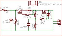
I find that with a gyrator on the plate, a simple ripple eliminator, capacitance multiplier, or "electronic choke" as shown kills all the power supply junk down below -120 dBu on the output of a single stage D3a amp at 30 dB gain. (Q2 is just for short circuit protection and set at 1.5X normal current draw)
For higher gain e.g. microphone or phono input stages a good shunt regulator is needed in addition.
Cheers,
Michael
Attachments
In these builds I will use a small circuit board to hold the gyrator and tube socket in close proximity. It will also provide a more stable base to add the elastomeric mechanical isolation. The initial reason was to be able to switch anode loads easily for listening comparisons.
The mechanical isolation methods I have considered include your suggested method above. The simplist method is to use some viton or similar o-rings and suspend it like a trampoline.
In my test bead the Kepco is seperated from the test bed by 1M. The SSHVSR is seperated form the gyrator by 30cm. (So I have room to work on the circuit without hitting things that are hot). So lead length certainly creates a hum pick-up issue.
Michael,I'm interested in mechanical isolation. I find that the D3a likes to ring at 15 KHz when excited in the right way. I'm thinking a metal-viscous-metal sandwich carrying the tube sockets, mounted on viscous polymer isolators.
For magnetic shielding I'm looking at some of the materials from lessemf.com wrapped around a toroid. But that shouldn't be an issue for you unless you are using a low level input transformer.
I'm also surprised that you're seeing a high level of power supply artifacts in a low gain line amp. Is your base case a simple RCRC filter? Also a little surprised to see so much 60 Hz left over. Maybe you have a ground loop somewhere. Nothing beats a good star ground with short local rectifier loops in the power supplies.
I find that with a gyrator on the plate, a simple ripple eliminator, capacitance multiplier, or "electronic choke" as shown kills all the power supply junk down below -120 dBu on the output of a single stage D3a amp at 30 dB gain. (Q2 is just for short circuit protection and set at 1.5X normal current draw)
For higher gain e.g. microphone or phono input stages a good shunt regulator is needed in addition.
Cheers,
Michael
Good thoughts about vibration isolation. In my world of vibration isolation at pumps, boilers and the like we use heavy inertia bases mounted on springs. Sometimes for lighter items we use pads of rubber and cork. Layers of differing density materials do wonders for vibration isolation. For my amplifiers I use feet made of Pink Pearl eraser, closed cell Neoprene and cork trivet (from Ikea). These isolators do well keeping out transformer hum/vibration.
DT
All just for fun!
Michael,
Good thoughts about vibration isolation. In my world of vibration isolation at pumps, boilers and the like we use heavy inertia bases mounted on springs. (...)
DT
All just for fun!
Indeed, there's no substitute for sheer mass.
The last industrial vibration issue I was involved with concerned some pulsation dampeners on the discharge side of 3 cylinder recip pumps pushing ammonium carbamate at about 3000 PSI. These bottles were about 20 inch diameter and maybe 36 inches long with > 2 inch wall thickness. The pulsation kept shaking their mounting pads apart. The solution as I recall was a huge reinforced concrete mass about 3 feet by 4 feet sunk into the ground beneath, which the bottles were heavily anchored into. The piping snaked around in a big 180 degree arc to isolate the pump from the bottle.
Hopefully this will be an easier problem but the lesson about mass is one I'll not forget.
I can see digging a hole in the living room. NOT
Hello SGregory,
While you are working on your project let me tell a DIY vibration tale.
A friend and I were drinking a totty at his home. We were sitting there discussing the loud noise caused by the air pump for his salt water fish tank. The tank and pump sat on a sturdy room divider. The pump shook the room divider that resonated and the sound filled the room. The solution we came up with was a solid chunk of oak from a packing crate. We drilled a neat recessed hole near each of the four corners of the chunk of wood installed a coil spring in each hole put the air pump on the wood block and the noise was gone. You too can do this at home.
Amazon.com: 200 pc Spring Assortment Set Hardware Tools Springs: Home Improvement
DT
All just for fun!
- Status
- This old topic is closed. If you want to reopen this topic, contact a moderator using the "Report Post" button.
- Home
- Amplifiers
- Tubes / Valves
- Gyrator Frequency Response?