![IMG_0047[2].jpg](/community/data/attachments/173/173263-198fd645b30b0763a4fcbc71e96e45a6.jpg)
Please give us more info.
Is this a commercial amp?
Is it home built?
Why are the tubes out of it?
Where did you get it?
Do you have any information at all about the amp?
Can you take more/better pictures of it?
Can you take a picture of the insides where the small tubes connect?
Is this a commercial amp?
Is it home built?
Why are the tubes out of it?
Where did you get it?
Do you have any information at all about the amp?
Can you take more/better pictures of it?
Can you take a picture of the insides where the small tubes connect?
I don't have any information on the amp.
I attached pictures of the inside.
I met up with SY and he looked at the amp for me. He said that the front tube is 12AU7 or 12AT7. The middle and back tubes are 6CG7. But as I mentioned, The middle socket will not light up the 6CG7.
I attached pictures of the inside.
I met up with SY and he looked at the amp for me. He said that the front tube is 12AU7 or 12AT7. The middle and back tubes are 6CG7. But as I mentioned, The middle socket will not light up the 6CG7.
![IMG_0048[1].jpg](/community/data/attachments/173/173286-8a62a7f80843e01258cad05fc08d48a7.jpg)
![IMG_0049[1].jpg](/community/data/attachments/173/173303-0c60aa8f45eaf7deb1de2a3a502e2fe7.jpg)
![IMG_0050[1].jpg](/community/data/attachments/173/173316-ba3ef77f1480679db477f8881b1b5c8b.jpg)
![IMG_0051[1].jpg](/community/data/attachments/173/173333-fef34a17aab87dbae1433b63c7bcf91e.jpg)
I got the following measurement from the 3 small tube sockets:
Front: Plate is 420 VDC, Grid is unknown, heater is 7 VAC
Middle: Plate is 948 VDC (that is right), grid is 420 VDC heater is 7 VAC.
Back: Plate is 443 VDC, Grid is unknown, One heater is 7 VAC and the other is around 3 VAC.
The two wires going to the grid of both power tube is coming from the back small socket.
I got the following measurement from the 3 small tube sockets:
Unfortunately, the voltage measurements will be meaningless until you've got all five tubes installed and drawing current. Otherwise you are just measuring unloaded supply voltages, which will be much higher than what you will find during normal operation.
If you want to measure voltages, you can (carefully!) look for the heater pins and confirm that against the expected locations based on the tube's data sheets. Heater voltages for the types you've mentioned should be 6.3v or 12.6v.
What you really need to do is trace out a schematic, based on hours of staring at the underside wiring of the amp. An ohmmeter will be helpful too. Once you have a schematic, someone here might be able to suggest reasonable tubes to put into each of the driver sockets.
Good luck!
I met up with SY and he looked at the amp for me. He said that the front tube is 12AU7 or 12AT7. The middle and back tubes are 6CG7. But as I mentioned, The middle socket will not light up the 6CG7.
It's possible the middle photo is 6CG7. The heater wiring goes to pins 4 and 5, which would fit. There are two film type caps, presumably coupling caps, going to pins 2 and 7. That would be the grids. There are two good size resistors at pins 3 and 8, which could be cathode resistors. But what is going on at the plates? That should be pins 1 and 6, but I cannot see clearly from your photo. Pin 1 has a red wire that goes where? Pin 6 is completely obscured.
Last edited:
In real life, the first tube was wired like a 12A*7 with a 6V supply (between 9 and 4-5). The second two tubes had heater wiring right to 4 and 5. Plate resistor in the first hole was something like 47k, so I speculate that it's 12AT7 or 12AU7. Several parts were broken.
Really, this amp, given the amateur construction, total lack of documentation, dangerous voltages, but superb iron, would be best rebuilt top to bottom. Man laid out quite a piece of money for it but his is at present admittedly not up to a redesign/rebuild; it's going to be a long-term project, involving much study and experimentation (which is NOT what he wanted to hear). My advice to him when he visited was to pick up a copy of "Valve Amplifiers" and start studying. Or to find an advanced designer and sell off the amp for parts (the Tango iron is easily worth enough to cover his cost for the amp).
Really, this amp, given the amateur construction, total lack of documentation, dangerous voltages, but superb iron, would be best rebuilt top to bottom. Man laid out quite a piece of money for it but his is at present admittedly not up to a redesign/rebuild; it's going to be a long-term project, involving much study and experimentation (which is NOT what he wanted to hear). My advice to him when he visited was to pick up a copy of "Valve Amplifiers" and start studying. Or to find an advanced designer and sell off the amp for parts (the Tango iron is easily worth enough to cover his cost for the amp).
Hi Stuart, I am glad you joined.
I will definitely buy and read that book.
I don't want to get into building amplifiers. I don't think there is anything wrong with the amp. I just need to figure out the tubes required. If I figure out the tubes and the amp doesn't work then I will figure something else.
You are absolutely right; it would be best to rebuilt from top to bottom by a GOOD builder. Sure, I would like to have the amp rebuilt in better design and maybe tube rectified and a nice chassis but that option is expensive and I do not know anyone who can and will do it.
I don't think there is anything wrong with the amp. I just need to figure out the tubes required.
Keep taking photos of the underside wiring. Try to get some shots from angles that show all the socket pins. If your camera has a macro mode, use it. Don't zoom in, or the pics won't be in focus. If we had some better photos, maybe we could help you figure out the schematic.
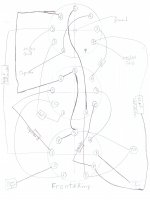
Okay I will do that. I am also drawing out the sockets wiring.
I think you are right. SY also said that it is 6CG7. The middle photo is of the BACK socket. That socket will light up a 6CG7.
It's possible the middle photo is 6CG7.
I think you are right. SY also said that it is 6CG7. The middle photo is of the BACK socket. That socket will light up a 6CG7.
I don't have any information on the amp.
I attached pictures of the inside.
I met up with SY and he looked at the amp for me. He said that the front tube is 12AU7 or 12AT7. The middle and back tubes are 6CG7. But as I mentioned, The middle socket will not light up the 6CG7.
Check to see which pins have the heater voltage on them and see if this matches a 6cg7.
- Status
- This old topic is closed. If you want to reopen this topic, contact a moderator using the "Report Post" button.
- Home
- Amplifiers
- Tubes / Valves
- Which tube does my amp use? 12AU7 12BH7 12AX7 6CG7 others?