I'm building another lightweight for my workshop. B/c of what I have on hand, the output will be three bottles of 6DJ8s in parallel, or six triodes. These tubes are prone to oscillations so I have decided to use plate stoppers to connect the plates together. But then I wonder if I should add some small resistors on each cathode as well? I need to connect the cathodes with something anyways, and using a 20ohm CC may be just as good as a wire.
(I have a bunch of 20 and 50ohm carbon comps, and I will use 50ohm CCs on the plates)
Any views on this? Am I overdoing it with stoppers on all three electrodes?
Thanks
(I have a bunch of 20 and 50ohm carbon comps, and I will use 50ohm CCs on the plates)
Any views on this? Am I overdoing it with stoppers on all three electrodes?
Thanks
What Allen said, but... like him, I've built a lot of boxes of gain with ECC88-oids. With a grid stopper right at the grid pin and good local bypassing, I haven't had one in common cathode oscillate on me. Likewise, with a grid stopper and a cathode stopper between cathode and output (and good local bypassing), I haven't had a cathode follower oscillate either. I generally use carbon comps for stoppers, but that's more of a matter of following precedent than anything systematic on my part.
YMMV. If you run into problems, resistors are cheap.
YMMV. If you run into problems, resistors are cheap.
Yeah, I guess u're both right. It'll probably depend on my mood right at the moment the soldering starts. I've had these tubes oscillate in parallel before, and plate stoppers was the easy fix. Right now I'm leaning towards having 50ohm stoppers on plate and 20ohm on the cathodes, and 400ohms at the grids. I need to connect all electrodes with something anyways, and it might as well be a resistor vs a wire.
But I just wondered if some of you HF guys had a definite opinion.
But I just wondered if some of you HF guys had a definite opinion.
It seems to me that a three-terminal device like a triode only needs stoppers on two terminals at most, and these should normally be the input and output terminals. My advice would be to use stoppers to prevent UHF oscillation, and good layout and decoupling (i.e. good up to VHF) to stop lower frequency parasitics. Remember, the 6DJ8/ECC88 was designed to give useful amplification up to about 1GHz!
I'm not certain it is quite as simple as that. At UHF a valve does not behave exactly like the low frequency model, as parasitic reactances can dominate. Neither does a resistor. It is generally better to ensure that the cathode is well-grounded, as inductance here can cause unwanted phase shifts. The exception, of course, is CF when it is the anode which needs to see a good RF ground.
Oscillations in a triode (or MOSFET), at high frequency occur though unintentional feedback paths, especially from anode circuit to grid circuit. The 180 degree phase relationship between these two mean that you only need to find a frequency where the effective coupling between the two electrodes gives an effective gain of 1. That satisfies perfectly the operating condition for an oscillator.
To get a gain of 1 between anode & grid you need sufficient electromagnetic coupling between the two, and a fairly high impedance at the grid, or gate (MOSFET), base (BJT).
A grid stopper works by presenting a lowpass filter at the "oscillator" input, reducing the effective gain at potential oscillation frequencies. It's an RC filter formed with the Miller-boosted capacitance of the grid. It is vital to have the stopper very close to the input pins, or else the electromagnetic fields can couple to the grid side of the stopper, bypassing the filtering effect.
A stopper in the anode circuit effectively prevents "transmission" of electromagnetic fields at high frequencies. It forms an RC lowpass filter with the anode capacitance (looking inward) and with circuit capacitance (looking outward) - an unbalanced pi-filter.
The cathode circuit is very low impedance compared to the grid, and so its susceptibility as an HF receiver is very poor. And because its voltage swings are usually much lower than the anode's, it is much less effective as a transmitter too.
It's possible to contrive circuit conditions where a cathode stopper would be effective, but for most configurations, it's near to useless. A grid stopper is almost always the correct way to go, you just have to implement it correctly:
- mounted so as to present the MINIMUM amount of conductor attached to the grid pin. The shorter the effective length, the weaker the coupling will be.
- Correct value: It's hard to judge the effective gain at oscillation frequency, and hence the degree of Miller effect, but aiming to produce a time constant of 5 to 10us will usually be safe for audio, based on the datasheet value for input capacitance.
- Construction. Avoidance of inductive parts is worthwhile - even low values of L will form a series-resonant LC at some frequency, and U/VHF triodes like ECC88 may well amplify at that wavelength. So SY is right to adopt carbon composition, as these are very low inductance. 1206 chip resistors also work well.
- Stubborn cases can often be suppressed even better using chip ferrite parts such as the MuRata BLM21A102S or its near relatives. These are not inductors, they are frequency-dependent resistors, and possess very useful cutoff characteristic. Just be careful to mount them rigidly, eg on a piece of FR4, as they may generate noise under vibration.
Avoidance of inductive parts is worthwhile - even low values of L will form a series-resonant LC at some frequency, and U/VHF triodes like ECC88 may well amplify at that wavelength. So SY is right to adopt carbon composition, as these are very low inductance. 1206 chip resistors also work well.
Carbon and metal film resistors above ~10 ohms are low enough inductance that they are regularly used in GHz bandwidth circuits, as long as you keep the body (and leads!) close to the ground plane.
In the analysis of a common anode (or collector or drain) amplifier, the input (grid / base / gate) takes on the phase rotation of what load is presented at the output (cathode / emitter / source). If the output is bypassed (capacitive), the input is negative resistive. An input "stopper" neutralizes this resistance. This also suggests that an inductive load will have the same effect, i.e., put a few uH RFC in the cathode and you'll be set (assuming the RFCs don't talk to each other, a good reason to get self-shielding types).
Tim
Oscillations in a triode (or MOSFET), at high frequency occur though unintentional feedback paths, especially from anode circuit to grid circuit. The 180 degree phase relationship between these two mean that you only need to find a frequency where the effective coupling between the two electrodes gives an effective gain of 1. That satisfies perfectly the operating condition for an oscillator.
Not enough. More than one capacitance is needed. For example, grid to cathode, and cathode to ground can cause needed phase shift, then input wire inductance plus input source capacitance give a tank. Add a grid stopper, and oscillations stop.
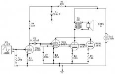
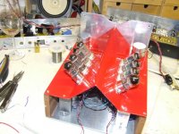
Well, I finally got my 'shop-amp' done. I skipped the plate stoppers, only used the usual grid stoppers, and separate cathode resistors, which I suppose act as 'cathode stoppers'. Being a flea power amp, it makes just under 1watt, I havent bypassed the cathode resistors since I dont need the gain. That gives some local NFB, which I don't mind, and ensures each triode operates within estimate.
I used what I had laying around, which is how most of the amps I build for myself end up being built.
I paralleled 3 5687 triodes in the output and used some 5k:8 Edcors I had. Unfortunately the only PT I had only gives me 170volt for B+. But the work shop only needs a watt so no real worries. With this low B+ I really don't need 3 5687s, but I don't like V-6s.
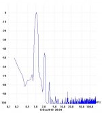
As is it sounds pretty damn good. Measurementwise it has nice low distortion till I pass 2.5V rms where the higher Hs start popping in. Max swing is +-4V into 8ohms. The 5687s wont let the plate voltage swing lower than about 80V without higher harmonics showing up. With some grid drive I imagine I can swing them a little lower for half a watt more, but I'm not that desperate.
Either way, sounds really nice, highly recommended but if doing it again I'd buy a new PT with proper B+ voltages, somewhere around 250-300volts.
The Edcors are great for the price, they are the real cheap XSE-15 types, and I measure -3dB corners at 15Hz and 54kHz. Not bad for those OTs.
I used what I had laying around, which is how most of the amps I build for myself end up being built.
I paralleled 3 5687 triodes in the output and used some 5k:8 Edcors I had. Unfortunately the only PT I had only gives me 170volt for B+. But the work shop only needs a watt so no real worries. With this low B+ I really don't need 3 5687s, but I don't like V-6s.
As is it sounds pretty damn good. Measurementwise it has nice low distortion till I pass 2.5V rms where the higher Hs start popping in. Max swing is +-4V into 8ohms. The 5687s wont let the plate voltage swing lower than about 80V without higher harmonics showing up. With some grid drive I imagine I can swing them a little lower for half a watt more, but I'm not that desperate.
Either way, sounds really nice, highly recommended but if doing it again I'd buy a new PT with proper B+ voltages, somewhere around 250-300volts.
The Edcors are great for the price, they are the real cheap XSE-15 types, and I measure -3dB corners at 15Hz and 54kHz. Not bad for those OTs.
Attachments
I find the ECC88 Cathode follower config is particulary prone to self oscillations around 470Mhz..I use small ferrite beads and carbon res at the grid pins and if a CCS is used on the cathode, an "output resistor of 50ohms".
As SY suggests, the shortest decoupling route to reduce self inductance from valve tag to chassis.
Ironically, the wire lead inductance inside the tube is nearly longer than the external with components !
richy
As SY suggests, the shortest decoupling route to reduce self inductance from valve tag to chassis.
Ironically, the wire lead inductance inside the tube is nearly longer than the external with components !
richy
- Status
- This old topic is closed. If you want to reopen this topic, contact a moderator using the "Report Post" button.
- Home
- Amplifiers
- Tubes / Valves
- plate stoppers or cathode stoppers?