Hello,
A few months ago I built a clone of a headphone amp which I had previously owned. I think everything went ok and the amplifier sounds pretty good. However, after a lot of reading I think the design is far from optimal. Particularly the input stage, where a 6SN7 is driven with too little current and voltage.
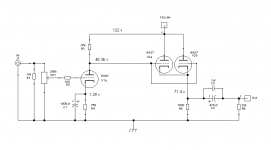
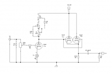
I have drawn a couple of schematics using CCS loading and LED biasing of the input tube, one dc coupled as the original and one ac coupled. The first one improves a bit the input stage but still drives the tube and also the LED with too little current. The AC coupled design allows me to increase the current from 2ma to 5ma and to increase the plate voltage from 48 to 90 volts but now I have a coupling cap. Which one is better?
Thanks in advance for your help.
Diego
A few months ago I built a clone of a headphone amp which I had previously owned. I think everything went ok and the amplifier sounds pretty good. However, after a lot of reading I think the design is far from optimal. Particularly the input stage, where a 6SN7 is driven with too little current and voltage.
I have drawn a couple of schematics using CCS loading and LED biasing of the input tube, one dc coupled as the original and one ac coupled. The first one improves a bit the input stage but still drives the tube and also the LED with too little current. The AC coupled design allows me to increase the current from 2ma to 5ma and to increase the plate voltage from 48 to 90 volts but now I have a coupling cap. Which one is better?
Thanks in advance for your help.
Diego
Attachments
Enhancement MOSFET easy to find.
MJK self-serving gyrator thingie.
Bootstrap back from output cathode.
LED and good caps for sure! If they do
their job well, elkos ain't hurting nuthin.
If they don't, big elko is extra insurance.
C2 might also benefit to be 470+47+1?
Ditch C2 if LED curve don't bother you.
Omitting gate and grid stoppers for unity
followers was a gamble, but probably OK.
Anodes are tied to B+ and don't swing,
further stabilized by cathode feedback.
Accidentally forgot gate protect zenier!
That oversight still needs fixed for sure.
I have not properly mathed any resistor
values, nor plugged in triode models to
run a sim of what the currents might be.
It might be possible to direct couple the
gate of M1 to V2's cathode? If V2's neg
grid bias is higher than M1's positive gate...
Attachments
Last edited:
Not quite sure if this bias would work or not?
Again I forgot to do something with C2.
M1 + D2 could be a BJT just as easy...
Then V2 would need only a very small
bias to exceed 0.66V, and/or the CCS
POT2 could then trim up to a slightly
higher value. What say MJE340?
Again I forgot to do something with C2.
M1 + D2 could be a BJT just as easy...
Then V2 would need only a very small
bias to exceed 0.66V, and/or the CCS
POT2 could then trim up to a slightly
higher value. What say MJE340?
Attachments
Last edited:
In the amplifier I built without the CCS the currents are 1.8 ma through the 6sn7 and 70 ma through each pair of 6as7 triodes.
I forgot to mention I'm gonna use the amp with Sennheiser HD800s which have an impedance of 300, so that's why I want to use just the biggest MKP I can fit in.
I forgot to mention I'm gonna use the amp with Sennheiser HD800s which have an impedance of 300, so that's why I want to use just the biggest MKP I can fit in.
In the amplifier I built without the CCS the currents are 1.8 ma through the 6sn7 and 70 ma through each pair of 6as7 triodes.
I forgot to mention I'm gonna use the amp with Sennheiser HD800s which have an impedance of 300, so that's why I want to use just the biggest MKP I can fit in.
The big 47 could and should still be your best MKP. Heck, why not?
Like I said, if even one quality cap does like you think: The others in
parallel won't see any AC, and can't do anything to hurt the sound.
Only if that 47 don't pull its weight, then others are there for support.
Neither 470 elko, nor a 1uF film are likely to eat up a lot of space.
C2 is totally ditchable, if you dump some extra mA into the IRLED.
Want to put that LED on the lowest impedance part of its curve.
I'm assuming some IR has about the 1.2V you are looking for?
Temped to dump R4's 70mA into it, but that might be positive FB.
If V1's heater had its own 6.3VDC supply, that might be a good
place to steal a few mA. Something like 50mA is about optimal.
If its really only gonna be 1.8mA, maybe a NiMH battery could
stand that much continuous trickle charge? They got a catalyst
to recombine water if the overcharge isn't too fast. I do not
know how a battery's internal resistance might actually sound?
Why am I not asleep?
Last edited:
With trickle charge battery bias.
Not so obviously: I'm thinkin solder tabs, no springs...
I read that Sanyo 2500mAH is built to survive 250ma?
So 1.8ma should theoretically be no challenge at all.
Theoretically, yeah...
---- edit ----
I'm just now looking at 6AS7 curves and figure around
15V drop across POT2. 2K5 is too small, maybe 25K...
Attachments
Last edited:
You may use couple of resistors instead of transistor. The same dynamic load, the same positive feedback from cathode follower, but without additional transistor with it's non-linearities.
The transistor would be at constant current too. Only Early to worry about.
You mean bootstrap two 22K resistors in the middle with yet another cap???
I don't see that RC delay being better linear then the worst direct coupled
transistor on earth. OK I exaggerate, its better than 2N3055, but not much.
And then we back to needing bootstrap caps of supreme quality.
Oh wait, maybe you mean resistor direct from V2 cathode! Yeah, I see it now.
Whats 1.8mA stolen away from 70mA? We don't need no stinkin' tranzeestor.
V2's cathode is 16V higher than V1's plate, and they don't have to operate
at the same current. The remaining 68ma dumps through R4.
Last edited:
Freakin' genius! I hope someone pays that man's salary.
Got a few of them FDA banned Four Loko in the trunk.
Need to bust out and celebrate, if taste don't gag me.
Man, I hear that stuff is nasty.
I don't appear to be sleeping tonight anyway...
-----
Nevermind the 6AS7 curve set. Its clear in Diego's
very first schematic that V2's cathode is 23V higher
than V1's plate. Assuming real live measurements?
25K still good for POT2, even closer to the middle.
We need 12K7 thereabouts.
Attachments
Last edited:
I hope someone pays that man's salary.
Nobody can afford a genius, so all geniuses are jobless...
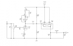
Here you go:
Attachments
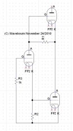
Please disregard value of R3: Rimu Schematics puts default 1K value.
Couple of resistors may be added: one in anode of 1'st triode to B+, and another to cathode of the right bottom triode, to better fit some particular tubes and their curves, but it's not necessary...
Happy Thanksgiving!")
Couple of resistors may be added: one in anode of 1'st triode to B+, and another to cathode of the right bottom triode, to better fit some particular tubes and their curves, but it's not necessary...
Happy Thanksgiving!

R1 has constant current drawn across constant voltage drop.
Same constant current then through R2 and/or grid(s) of V3.
Suggesting V3 dumbed down to single triode plate resistance in
case #1, or something slightly closer to a current source in
case #2 (cascode of three triodes with constant grid voltage).
Why isn't V3 an active player here? Am I missing something?
Is CCS supposed to be better than 1K resistor? Cathode of V2
will still see current variations into 300ohm headphone load.
Drive V3 from error sense resistor above plate of V2, as a
White Cathode Follower, now maybe you got something...
V3 would then hold V2 at constant current by dumping the
dynamic opposite of the headphone load.
Last edited:
Direct coupled method for top triode to also operate at constant current.
Hopefully, PNP current dumping could dispose of observed load variations?
Note: Even if we set currents equal, voltage drops won't necessarily be.
Voltage on V1a is set by Mu, and the remainder still has to add up to B+.
Wanna tweak for equal voltages? Result: slightly higher bias than 1.8ma,
but I don't see any reason that would be a problem.
MJE350 might be a poor choice, would have to cherry pick a good one.
Darlington like TIP147 does not offer the voltage we need. Or mix your
own pair of PNP discretes. Base current could be high as 2.3mA if you
randomly grab MJE350 of the minimum spec, min useless for 1.8mA CCS.
The good news, it will be dissipating 6 or 7 Watts, so HFE will have the
benefit of toasty warmth. Heatsink required. No worry, rated for 20W.
I've thrown two new resistors at the problem of current measurements.
R4 updated to 600 to maintain 70mA, necessitated by top triode change.
I might have made a mistake, R4 might still need to be 1K, not certain...
Might be technically better than the previous one? But I kinda prefer
simplicity over obsessive constant current everywhereness...
Attachments
Last edited:
R1 has constant current drawn across constant voltage drop.
Not exactly. Triode is not ideal, and loaded on not ideal constant current source. This not ideal error is amplified by right bottom triode supplying some error correction. Right handed triode has high output resistance, so it looks more like modulated current source decreasing variations of current through cathode follower.
The detected error at R2 has shrunk by 1/(Mu-1), V3 will need a lot of gm to fix anything!
Make V3 MOSFET or BJT, and you have Triodlington, and a situation where the current
variance of error in V1 is dumped by sand, leaving even more constant current in Triode
V1, which is the loadline with our best hope for Mu...
Make V3 MOSFET or BJT, and you have Triodlington, and a situation where the current
variance of error in V1 is dumped by sand, leaving even more constant current in Triode
V1, which is the loadline with our best hope for Mu...
Last edited:
The detected error at R2 has shrunk by 1/(Mu-1), V3 will need a lot of gm to fix anything!
Make V3 MOSFET or BJT, and you have Triodlington, and a situation where the current
variance of error in V1 is dumped by sand, leaving even more constant current in Triode
V1, which is the loadline with our best hope for Mu...
Right handed triode has high mu. And sand current mirror can be used also.
- Status
- This old topic is closed. If you want to reopen this topic, contact a moderator using the "Report Post" button.
- Home
- Amplifiers
- Tubes / Valves
- Please help me improve my headphone amp