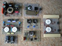
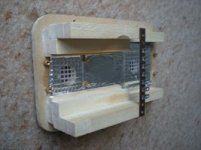
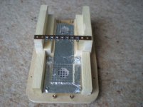
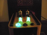
Just for fun here is a strip board project just completed!
I just wondered what I could power with a laptop power supply.
So here are the boards, they were modified through the project.
")
Regards
M. Gregg
I just wondered what I could power with a laptop power supply.
So here are the boards, they were modified through the project.
Regards
M. Gregg
Attachments

I had a few problems with the regulator this was solved here:
http://www.diyaudio.com/forums/tubes-valves/174667-has-anyone-used-regulator.html
This has been flashed to Gnd and is still working OK.
http://www.diyaudio.com/forums/tubes-valves/174667-has-anyone-used-regulator.html
This has been flashed to Gnd and is still working OK.
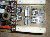
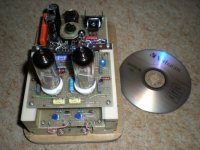
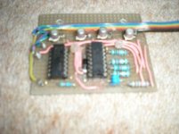
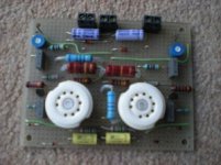
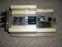
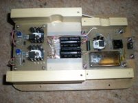
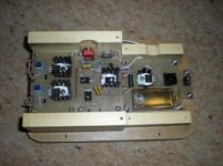
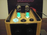
ECC88 Aikido section in place with 350V to 250V regulator. Inverter section installed with soft start, DC heaters lifted using Recom inverter isolation. Staged heater start circuit with current limit and thermal "solid state fuses". HT switched from heater circuit by Triac.
Attachments
Last edited:

Member
Joined 2009
Paid Member
What's all that about?
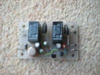
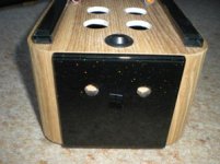
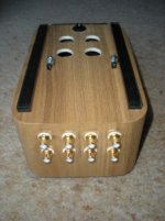
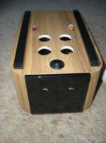
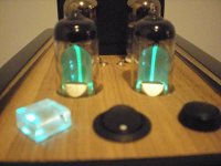
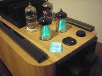
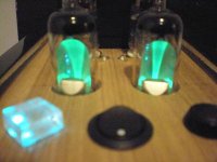
The input selector uses a decade counter with debounce circuit, this drives the relays on the input board. Each output from the decade counter drives a different colour LED all mounted under the glass diamond on the front. So you can link the colour to the input selected. IE green Ipod, yellow CD, red tuner, ect. Just a bit of fun the glass changes colour.
Regards
M. Gregg
Looks fantastic ! - schematics ?
Thank's for the kind comments!
I must admit I tend to pick up a piece of Glass fiber strip board and with a pencil and paper sketch the circuit and build. I will look at putting some circuits down on paper and posting some of the schematics and links I used.
Regards
M. Gregg
OK.
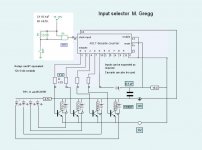
I have "created in p. point and converted to jpeg" the input selector section schematic.
I must admit I don't know why anyone would use a rotary switch when you can position a single push button any where on the chassis and have the relay board next to the phono socket inputs. The 18K for the reset is not critical, however if the value is to high or low it will effect the current drain from the chip or not allow a "0" for the count. The 0.1uf from supply to reset ensures that the selector always starts at output "0". It is easy to modify for as many inputs as required!You could use output "0" as mute at start and move the inputs to output 1,2,3,4 etc.
Regards
M. Gregg
Attachments
Last edited:
Sorry,
I said I would post some of the circuits.
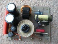
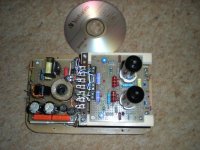
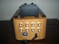
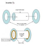
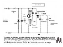
Here is the HT inverter it is very simple and with a filter it powers the Aikido section the regulator and the EM80's. I found it interesting because it uses a Tx that is easy to make. Also it does not supply HT if no load is connected, so a heater failure turns off the HT.
Wind the HT coil first then insulate with tape and wind LT on top(Spread the windings across the Bead)!
Don't be tempted to "bolt through the bead with a steel pin" to secure it! Use a plastic pin or tyrap.
I know some people will say "regulation". It works well for me there is more noise from the regulator than the inverter! (mV)
The Inverter circuit was modified from this link. I found the reg they used to be of little use! Shorts take out the transistor. The one further back in the post Maida works well!
Inverter HT PSU
Regards
M. Gregg
I said I would post some of the circuits.
Here is the HT inverter it is very simple and with a filter it powers the Aikido section the regulator and the EM80's. I found it interesting because it uses a Tx that is easy to make. Also it does not supply HT if no load is connected, so a heater failure turns off the HT.
Wind the HT coil first then insulate with tape and wind LT on top(Spread the windings across the Bead)!
Don't be tempted to "bolt through the bead with a steel pin" to secure it! Use a plastic pin or tyrap.
I know some people will say "regulation". It works well for me there is more noise from the regulator than the inverter! (mV)
The Inverter circuit was modified from this link. I found the reg they used to be of little use! Shorts take out the transistor. The one further back in the post Maida works well!
Inverter HT PSU
Regards
M. Gregg
Attachments
Last edited:
- Status
- This old topic is closed. If you want to reopen this topic, contact a moderator using the "Report Post" button.
- Home
- Amplifiers
- Tubes / Valves
- Strip board project completed.