So, I have build a couple of SE stereo amplifiers using the ECL85. I will include the schematic for what I have currently. What I want to do is essentially use all the same transformers, choke, and power supply and substitute 6v6 for the pentode and a 12AT7-WA (I just have a bunch of these laying around) for the triode gain stage. I wanted to see if anyone had some experience running the voltage that low on the 6V6 and my power transformer is going to limit the current available for the power stage to about 30ma per channel (worked out just fine for the ECL85 but I think it is not going to be enough for the 6v6). Thoughts?
Attachments
I wanted to see if anyone had some experience running the voltage that low on the 6V6
I think your supply voltage is no wise low. Seems to be over 400 V.
Since the available current is limited, the output power will stay at the same level ( about 3 W ?) as with ECL85.
There seem to be absolutely too small cathode bypass capacitors at the pentode, only 6 uF. This will limit the bass response. Put min. 100 uF instead and you hear the difference.
Just to clarify that the supply voltage ends up being around 220-230v the transformer and the type of rectification really makes the transformer a 175-0-175.I think your supply voltage is no wise low. Seems to be over 400 V.
Also to address the capacitor size I ended up putting a 47uF cap since that is what I had in my parts bin. If I remember right on the schematic the reason I said min of 6 uf was for a 3db roll off that gives about 40Hz. I agree low end would suffer. 47 uf would give roll of of about 5Hz or so. Maybe I am missing something with this calc though?There seem to be absolutely too small cathode bypass capacitors at the pentode, only 6 uF. This will limit the bass response. Put min. 100 uF instead and you hear the difference.
I only get about 220v for the high voltage out of my power supply. 40-45ma x2 channels (80-90 ma) will overload the transformer.6V6 works good with 40-45 ma - 280-300v
Have very many people run a 6v6 at 200v (with the type of bias setup I have here) and about 30ma with success having a 6.6k ohm primary load to 13k primary ohm load?
I think that transformer would work well I was just trying to avoid buying another power transformer and using up the parts that I had on hand. I might have another power transformer that would give me the voltages and current capability that I am looking for. Maybe the best thing is to get a little bigger transformer?Hammond 269AX has 250 v - 100 ma on secondary coil. /cost about 39 $/
I use the Allied 6K56VG in my 6V6 Simple SE. It uses a 12AT7 for the driver. B+ is 325 volts using a 5AR4 rectifier tube. Probably around 350 volts with silicon. The transformer is $45 and is made by Hammond.
Search results for "6k56vg" - Allied Electronics
Search results for "6k56vg" - Allied Electronics
Or if you have another transformer that puts out 12v you could free up some of the iron in your existing transformer and not run the heaters off it. That may give you an added 25mA which should put you in the ballpark for the 6v6's. If you find you like it you can look at a permanent solution.
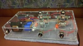
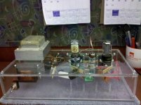
Well, after going through thanksgiving and working through the design. I had a spare transformer that was a little larger that could handle the voltages a little better. Here is a schematic of what I ended up going with. I am still up for some modifications if someone has any. Also I have one correction to the schematic that I have drawn. I have a choke from the diodes to the first capacitor. The choke is 7H and 240ohm. Let me know what you think. I have also included a picture of the amp. Thanks in advance.
Attachments
I have a choke from the diodes to the first capacitor.
If you still look for a bit higher anode voltage, put an electrolytic capacitor before the choke. This could rise the supply voltage a little.
Couple of other comments;
You could use separate cathode resistors at output tubes. This improves possible unbalance between tubes.
Since your output transformers are not the best for 8 ohms load ( too high turn ratio) you could also add a light NFB, for example by connecting the secondaries of the output pubes in series with the cathode resistors, (and with correct polarity).
Usually the linearity of the output stage is improved if some 470-680 ohms series resistor added between UL-tap and g2.
....by connecting the secondaries of the output pubes...
Should be: "for example by connecting the secondaries of the output transformers in series with the cathode resistors, (and with correct polarity).
...for example by connecting the secondaries of the output pubes in series with the cathode resistors...
I'd be worried about this too!

Ok I have sketched 3 different options. I think the one suggested was the middle option. I seems to me that global feedback is what was suggested to lower output impedance to help with the mismatched load. To do that I think I have to introduce local feedback at either the driver stage or the power stage. take a look and see what you think. Let me know if I might need to adjust the feedback network resistors. I can adjust the caps to get the low frequency cut off that I need. I like the looks of the first network I have shown but am not too familiar with adjusting the size of that resistor for optimum in this case. Let me know if I didn't get something correct or misunderstood someone. Thanks again.
Attachments
I would try the first (new) one with NFB from secondary of the OPT.
To adjust the proper feedback resistor is not big science.
Do this way:
1. Simply adjust your amplifier - without this NFB-resistor - to nearly max. undistorted output level and read the voltage ( I guess you have unversal meter with AC-ranges). You can use loudspeakers if you do not need resistive dummy load.
Take the test frequency, say 1 kHz from your PC's soundcard output.
There are many free "signal generator" -free SW available. (TrueRTA forexample).
2. Connect a 22 ... 100 kohms potentiometer to the place of NFB-resistor and adjust it to the voltage reading, which is between 0,3 ... 0,1 x the original voltage.
Value (0,3 x) represents some 10 dB NFB and value (0,1 x) represents 20 dB NFB.
3. Measure the value of the potentiometer and replace it with fixed resistor with same value.
Let me know if I might need to adjust the feedback network resistors.
To adjust the proper feedback resistor is not big science.
Do this way:
1. Simply adjust your amplifier - without this NFB-resistor - to nearly max. undistorted output level and read the voltage ( I guess you have unversal meter with AC-ranges). You can use loudspeakers if you do not need resistive dummy load.
Take the test frequency, say 1 kHz from your PC's soundcard output.
There are many free "signal generator" -free SW available. (TrueRTA forexample).
2. Connect a 22 ... 100 kohms potentiometer to the place of NFB-resistor and adjust it to the voltage reading, which is between 0,3 ... 0,1 x the original voltage.
Value (0,3 x) represents some 10 dB NFB and value (0,1 x) represents 20 dB NFB.
3. Measure the value of the potentiometer and replace it with fixed resistor with same value.
2. Connect a 22 ... 100 kohms potentiometer to the place of NFB-resistor
Correction: This potentiometer needs to be smaller. Try from 2k2 to 10 K.
So last night I went back with some of these suggestions to implement them. The first thing that I did was separate out the 6v6 bias. So they both now have 470uf caps and 500 ohm resistors. I then took out both cathode bypass capacitors off the 12at7's. I then fired up the circuit. It sounds golden.
I then went ahead and decided to put a filter cap before the inductor to see if I could get the high voltage up to about 350 or so. I put in a 67uf there and now my high voltage is at 460 or so. not so good on the 6v6. However not a bad place for a 6l6g right?
I then went ahead and decided to put a filter cap before the inductor to see if I could get the high voltage up to about 350 or so. I put in a 67uf there and now my high voltage is at 460 or so.
not so good on the 6v6. However not a bad place for a 6l6g right?I then went ahead and decided to put a filter cap before the inductor to see if I could get the high voltage up to about 350 or so. I put in a 67uf there and now my high voltage is at 460 or so.
Start with a 3-5uF cap and go from there.
I put in a 67uf there and now my high voltage is at 460 or so.
Not necessarily bad for 6V6 since your output transformer has a bit too high turns ratio for 8 ohms load. Now with 450 volts anode voltage the tube works at higer impedance level, assuming the anode current is at right (=lower) level.
Now your bias (cathode voltage) should be some 15 volts if cathode resistor is 500 ohms. If not, adjust cthode current to 30 mA.
And, yes I know the max. anode voltage rating is 315 volts, but so what.
Main issue is that the max. anode dissipation is not exceeded (too much).
Actually 6V6 may sound great with this unusual bias - anode voltage - load resistance combination.
Now your bias (cathode voltage) should be some 15 volts if cathode resistor is 500 ohms. If not, adjust cthode current to 30 mA.
I just now looked the tube data. Your cathode voltage should be higer, some 35 V to get 30 mA cathode current.
Are you sure the supply voltage really is 460 volts when 6V6 is drawing current too ?
I see. Yes that 460v reading came with the two 6v6 in the circuit and the addition of that 67uf cap. I also wish I had a couple of smaller value caps to see if that would reduce it, sadly the smallest one I have with that voltage rating is 47uf.
I see where if I had the same setup with a 500ohm resistor that I would have about 445V across anode to cathode and if it was set at 30ma that would give about 13.35W dissipation and an internal resistance of about 14.8k which would be about right for the turns ratio and an 8 ohm load. I also have a couple of higher wattage 1k ohm resistors if I end up in the wrong place current wise. I will see if I can get the circuit tamed tonight.
I see where if I had the same setup with a 500ohm resistor that I would have about 445V across anode to cathode and if it was set at 30ma that would give about 13.35W dissipation and an internal resistance of about 14.8k which would be about right for the turns ratio and an 8 ohm load. I also have a couple of higher wattage 1k ohm resistors if I end up in the wrong place current wise. I will see if I can get the circuit tamed tonight.
- Status
- This old topic is closed. If you want to reopen this topic, contact a moderator using the "Report Post" button.
- Home
- Amplifiers
- Tubes / Valves
- 6V6 SE VS ECL85