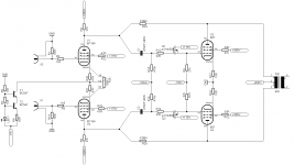
Here is my new creation, a 807 push-pull amp, supposed to give 60W in AB2.
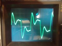
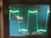
I added different plate to plate feedback resistors and measured the output of a 10kHz square wave, using a real speaker as the load of the amp.
I used a real speaker so I could demonstrate the effect of the dampening factor
Measurements could be repeated when I find the resistors to make a dummy load. (so i can calculate the real numbers..)
Another thing to consider is that when I use smaller feedback resistors, the voltage on the input pentodes rises. Perhaps i should have increased the current in this stage to get the same voltages on every measurement.
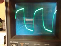
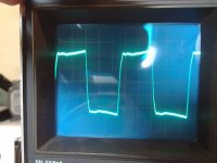
Here you will see the output of the 10k square, with no plate to plate feedback.
Clearly, the amp doesnt have a good dampening factor. (altough I find it sounds rather nice already)
I added different plate to plate feedback resistors and measured the output of a 10kHz square wave, using a real speaker as the load of the amp.
I used a real speaker so I could demonstrate the effect of the dampening factor
Measurements could be repeated when I find the resistors to make a dummy load. (so i can calculate the real numbers..)
Another thing to consider is that when I use smaller feedback resistors, the voltage on the input pentodes rises. Perhaps i should have increased the current in this stage to get the same voltages on every measurement.
Here you will see the output of the 10k square, with no plate to plate feedback.
Clearly, the amp doesnt have a good dampening factor. (altough I find it sounds rather nice already)
Attachments
Last edited:

Can someone explain to me what happens when I use a too small feedback resistor?
Plate voltage goes > 250V? maybe 270V?
What's happening is as the voltage drop across the resistors becomes less and less (as you decrease the resistance) there is very little remaning available driver headroom (voltage and current) to swing positive. Remember that the 807 plate voltage is decreasing as the driver voltage is increasing. It's running out of drive current.
Try coupling your feedback with capacitors to block the DC current from the 807 plate. If that doesn't do it you may need more than 5-7 mA idle current in the driver instead.
Or maybe the performance is great with the larger Rfb and you're golden!
Cheers,
Michael
Last edited:
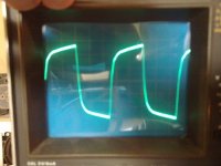
With a small feedback resistor you are simply putting a square wave through a limited bandwidth, so it gets rounded off. This is what you should see at 10kHz. With a higher resistor you are seeing OPT ringing at its HF resonance, as the anode impedance is too high to damp the resonance. This looks superficially better, but is actually less accurate.
I've tried this method on many power amps without real benefit. From a distortion view, each and everycase using good quality o/p transformers it made the 10 kHz sine distortion slightly worse, although it cleaned up the square wave ringing with the effect of reducing the already placed UL snubber values. In such cases, the application of global nfb (20dB) has such profound effects on the whole performance of the amplifiers that I dispensed with the configuration. I can only assume that the technique works best with lower quality output transformers, but one will find by altering the quiescent output stage current at 10kHz working this also has a profound effect on THD. i.e ye higher the quiescent current, the better looking squarewave and lower sine THD. Goes hand in hand. By tackling the 1st stage Zobel and the global feedback step response in a proper way I found I gives optimum results..........i.e nom 20dB circuit global nfb, the amplifier if designed properly should cope with another 15dB on top without any signs of oscillation or instability....into a resistive dummy load. It can be a tough test if the layout is poor. Alot of output stages, in my view run too light at higher audio frequencies which has a big effect on sound quality definition.
richy
richy
I have experimented with anode/anode fb many times, but no matter the improvements in measured performance, the amps always sound "thin".
No measurable bass roll off, but sound thin.
Anyone else experienced this?
Regards, Allen
No measurable bass roll off, but sound thin.
Anyone else experienced this?
Regards, Allen
Another thing to consider is that when I use smaller feedback resistors, the voltage on the input pentodes rises.
This is obvious since DC-voltage at anode of 807 is essentially higher than at the anode of the driver. The smaller the feedback resistor, the bigger current thru it will flow and results increasing anode voltage at the anode of the driver. Simply add a series capacitor.
Can someone explain to me what happens when I use a too small feedback resistor?
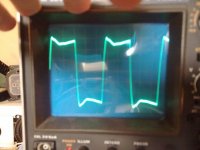
With small feedback resistors the higest frequencies seem to attenuate.
This can be seen as rounded edges of the square wave.
I would suggest you to experiment with some amount of global feedback (...10 dB) from the secondary of the output transformer AND also this shunt feedback, but only a little (3dB...). You could find a great combination.
By the way: You can get up to 70 W from an AB1-class PP-pair of 807.
Makes the whole construction much easier...
Can someone explain to me what happens when I use a too small feedback resistor?
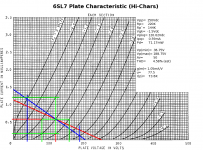
Reducing Rf has the effect of increasing the level of plate voltage fed back to the input. This has the effect of increasing the loading on the driver. Take a look at this loadline (attached). Without that local NFB, the load on the 6SL7 would simply be Rp || Rg:
220K || 1MEG= 180.33K
Connecting the local NFB makes that load look like 144K effective. In this case, the THD estimate is barely acceptable, however, since this is designed as part of an LTP you lose the even harmonics, and the 6SL7 should mainly be producing h2, so that works out. In the end, it worked out just fine. Adding more local NFB would have been pushing everything to the extreme, making even more distortion as the loadline grew more vertical, and 6SL7s don't have a helluvalot of current margin to spare.
I have experimented with anode/anode fb many times, but no matter the improvements in measured performance, the amps always sound "thin"... Anyone else experienced this?
No. Not my experience at all. With the 807-based design, the 807s like to make lots of higher order harmonics that sounds nasty running open loop -- Ozzy sounded really nasty. Fingernails-on-a-blackboard nasty. In the "white paper" O. Schade (the type's developer) on the 807 recommended feeding back 10% of the plate voltage to the grid. That's what I designed for, and that recommend was spot-on. It cleaned up a good deal of that open loop nastiness, and all that was required was some 6.0db(v) of gNFB to clean up the rest. The end result didn't sound thin at all.
May be if you over do it, then you might have problems, either due to excessive driver overloading, or may be 807s just don't like more than 10% fed back (there must have been a reason Schade recommended 10% as opposed to some higher figure).
Vixen Main Schemo
Attachments
By the way: You can get up to 70 W from an AB1-class PP-pair of 807.
Makes the whole construction much easier...
Hoo! That's pushing it. YOu really meant' AB2 ? 6.5K a-a; anode 600V screens 300V.Then you expect 80W.
richy
Hoo! That's pushing it. YOu really meant' AB2 ? 6.5K a-a; anode 600V screens 300V.Then you expect 80W.
richy
No. I mean AB1. With the following values:
- anode voltage 750 V
- screen voltage 300 V
- bias voltage -35 V
- g1 drive voltage 70 Vpp
- plate to plate load resistance 12k
- quiescent anode current 30 mA
- output power 72 W
This specs is from RCA 807 data (NOV, 5. 1954)
Here is one example of such design, Geloso G.3262. (75 W @ AB1)
http://digilander.libero.it/iw2dgs/bollettini/skemi/amplif/G-3262.png
There also an AB2 class version; Geloso G.3272 ( up to 100 W @ AB2).
You can see the cathode follower to drive the 807-pair.
http://digilander.libero.it/iw2dgs/bollettini/skemi/amplif/G-3272.png
http://digilander.libero.it/iw2dgs/bollettini/skemi/amplif/G-3262.png
There also an AB2 class version; Geloso G.3272 ( up to 100 W @ AB2).
You can see the cathode follower to drive the 807-pair.
http://digilander.libero.it/iw2dgs/bollettini/skemi/amplif/G-3272.png
OK- I have to admit- I don't get it.
This is the first time I've encountered feedback from the plates of the output to the plates of the driver- I'm not sure what this is supposed to do- What is the primary objective?
I've designed an amp that's differential throughout with 20 dB overall FB and was wondering if there'd be any advantage in keeping the O/P xfmr out of the loop by taking the overall feedback in differential mode, from the plates of the KT-88s to the grids of the input diff amp -but what I see here isn't that... but kinda-sorta.
Could someone take a moment to enlighten me, please?
The feedback really isn't to the plates of the drivers (though it may look that way). It's really back to the grids of the output tubes- the plate impedance of the driver is pretty high, so the feedback ratio reduces to the feedback resistor divided by the driver plate resistor.
Short feedback with minimal phase shift that linearizes output tubes and lowers output stage's output resistance, VS long path around the whole 2-3 stages plus transformer itself. Do you hear me now?
However, in my amps I use more than one feedback, but this local feedback around output bulbs helps a lot.
However, in my amps I use more than one feedback, but this local feedback around output bulbs helps a lot.
No. I mean AB1. With the following values:
- anode voltage 750 V
- screen voltage 300 V
- bias voltage -35 V
- g1 drive voltage 70 Vpp
- plate to plate load resistance 12k
- quiescent anode current 30 mA
- output power 72 W
807 operating points like these were intended for AM plate modulator duty where sonic performance is not a consideration. That's likely to put the finals close to Class B, and that'll give a lot more x-over distortion. They're after lotsawatts to AM modulate a ham rig where fidelity is neither needed nor legal.
Here is one example of such design, Geloso G.3262. (75 W @ AB1)
There also an AB2 class version; Geloso G.3272 ( up to 100 W @ AB2).
You can see the cathode follower to drive the 807-pair.
These are schemos for PA systems: another application where the premium is lotsawatts, not fidelity.
807s aren't gonna give you that much power and do it while sounding good.
OK- I have to admit- I don't get it.
This is the first time I've encountered feedback from the plates of the output to the plates of the driver- I'm not sure what this is supposed to do- What is the primary objective?
Local NFB represents a continuum between pure pentode operation and full-on pseudotriode operation. The local NFB serves two purposes: it linearizes the pentode final(s), making its AC plate characteristics more like that of a triode. It also serves to get the internal impedance down. Pents have very large r(p)'s that make for Hi-Z outputs, which you don't want in an audio amp since there is less damping of the speeks.
Local NFB is needed for certain power pents since these like to make too much of the higher order harmonics and can sound quite nasty running open loop. The 807-oids would fall into this category. O. Schade, the developer of the type, recommended local NFB. Other types (e.g. 6V6-oids, 6BQ6, possibly other TV horizontal deflection finals) don't make all that nasty higher order harmonics, and don't really require this extra help.
I've designed an amp that's differential throughout with 20 dB overall FB and was wondering if there'd be any advantage in keeping the O/P xfmr out of the loop by taking the overall feedback in differential mode, from the plates of the KT-88s to the grids of the input diff amp -but what I see here isn't that... but kinda-sorta.
The only reason to keep the OPT out of the gNFB loop is because you're either using a lousy OPT, and should replace it with a better one, or you're trying for insane levels of gNFB because you really like that solid state sound. I tried 20db of gNFB with one project, and, yup, it sounded no different from any Big Box store solid state amp.
Another project incorporates adjustable gNFB (0 -- 13db). Dialing in the full 13db is definitely tending towards that solid state sound. That might be OK for some types of music, but really makes Techno and Hard Rock and Metal sound "subdued". Around 6.0db is just about right.
I tried 20db of gNFB with one project, and, yup, it sounded no different from any Big Box store solid state amp.
But did the output sound like the input?
Just to put things in perspective, Futterman amps had upward of 40dB of feedback.
Wavebourn, Sy- Thanks a lot.
That's actually what I thought at first (said to self: "Why, all this is nothing more than local FB around the output stage!) but then I made more of it that there really is/was.
Not that it's easy to implement, impedances being what they are here.
Thanks for clarifying- I'll stay tuned to this interesting thread. -!
- Status
- Not open for further replies.
- Home
- Amplifiers
- Tubes / Valves
- plate to plate feedback - measurements