But did the output sound like the input?
Not hardly. The resulting sound was like throwing a heavy comforter over the speeks. Lyrics became noticeably harder to understand, fading into a bland background. With one song, there was a passage I knew was in there, and I didn't hear it at all. No sound stage, no stereo imaging, no fidelity. That was just plain hideous.
Just to put things in perspective, Futterman amps had upward of 40dB of feedback.
That's probably an artifact of speaker design from those days when speaker design really was a "black art", before Theil's research into speaker design. It took lots of gNFB to get that Zo way down there to tame those ill-mannered beasts with all their impedance surprises across the audio band. These days, it's not necessary, and that level of gNFB in a hollow state amp is way too much and really compromises the sonic performance.
Wavebourn, Sy- Thanks a lot.
That's actually what I thought at first (said to self: "Why, all this is nothing more than local FB around the output stage!) but then I made more of it that there really is/was.
Not that it's easy to implement, impedances being what they are here.
Thanks for clarifying- I'll stay tuned to this interesting thread. -!
There were other threads about this type of local feedback, discussing the topic in great details, including driver stage that is loaded on parallel feedback.
Today I have found the time to experiment some more..
I tried increasing the current in the LTP so the voltage is back at initial setting.
I tried using coupling capacitors so there is no need to change the current.
I tried to use a resistor network a la baby huey.
Results where close together with all different methods.
But the sound is better with no feedback, or just a very very little bit!
When I apply a large amount of feedback, the amp loses it speed, it doesnt have that nice punch anymore.. (I think that's what Allen described as thin)
I'm running out of ideas.. I dont want to use gNFB
When I apply a large amount of feedback, the amp loses it speed, it doesnt have that nice punch anymore.. (I think that's what Allen described as thin)
I'm running out of ideas.. I dont want to use gNFB
Then don't. Your design; you have to live with it. I don't.
My small experience is that the lower the output impedance the thinner and tighter the sound. Using lots of plate to plate will do that and so give a thinner sound. I do this approach with 6080 finals with 100% local feedback - these have amazing bass control compared to any other tube amp I have heard.
Speakers tend to be optimized for either tube amps or solid state amps and will tend to sound significantly different if not properly matched to their intended amp.
I also built a version of Gary Pimms Tabor using 807's but its intrinsic distortion never went away for my satisfaction, a brittle edge to everything - never spent much time on optimizing it though.
Just my thoughts
Shoog
When I apply a large amount of feedback, the amp loses it speed, it doesnt have that nice punch anymore.. (I think that's what Allen described as thin)
I'm running out of ideas.. I dont want to use gNFB
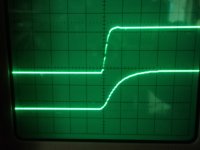
Why not ? Somethings not right here. That relationship goes completely against the grain. All amps using global feedback, use it to extend the frequency response, as such the slewrates become faster; one has only to look at 1kHz squarewave to see this with and with global feedback. The results are dramatic !
Pic with Square wave output of 100W power amp with global nfb (upper trace) and without (lower trace) . Rise time with feedback ~3.5uS.
Without the feedback, the response -3dB @ 10kHz !!; With it -3dB @ 55kHz. BIG difference. I fail to see the sounds "thin" connection. It must be something else to blame.
richy
Attachments
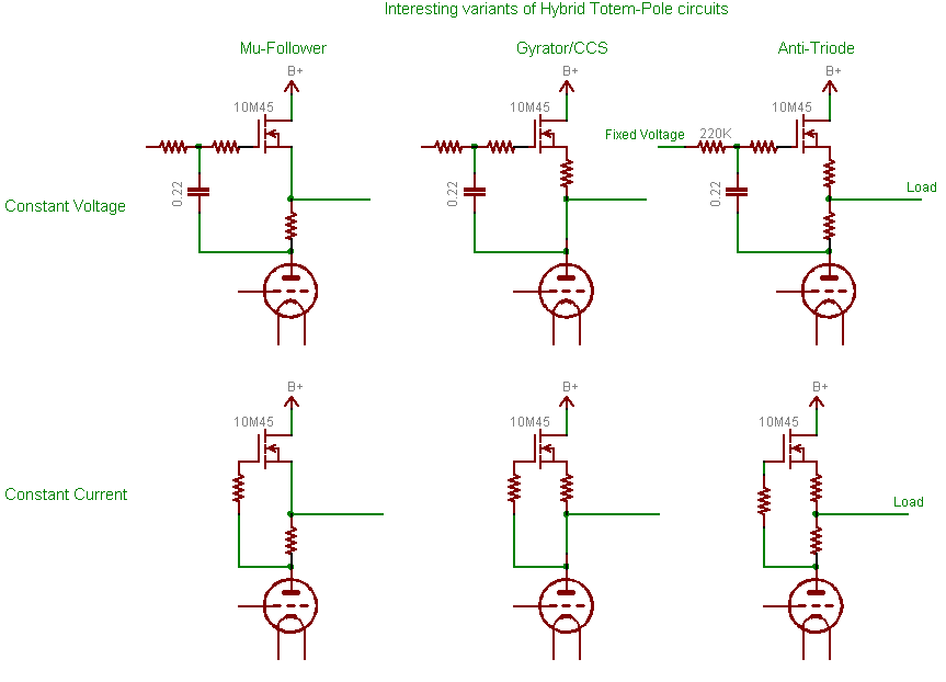
Also add gyrators instead of anode resistors. MJK has shown elsewhere how it should be done.
I tried this sometime ago using high transconductance unscreened tubes, the 6CL6,12BY7 gang, and with the minimal damping and excellent ft, self oscillation can be a problem. Beware of the layout using such gyrators with a near infinite AC load Z.
I tried this sometime ago using high transconductance unscreened tubes, the 6CL6,12BY7 gang, and with the minimal damping and excellent ft, self oscillation can be a problem. Beware of the layout using such gyrators with a near infinite AC load Z.
The feedback resistor connected to the output tube plate is an AC load and sometimes also a DC load for the driver pentode. It's very well controlled and I've not had any oscillation problems using 6CL6 or other high gm pentode.
I agree the thin sound and rounded 10 KHz square wave are not likely to be related except perhaps caused by a high output damping factor. Thin sound could simply be flat LF response. The square wave rounding could simply be your OPT response and gNFB would be needed to help out.
But what is the sine wave frequency response? Maybe the high end is good enough.
The driver voltage and current changes are not a bad move though. Gyrators wouldn't hurt either but none of that is likely to change the thin-ness or the rounding of the square waves at this point.
Cheers,
Michael
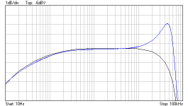
Wow, it is starting to make sense..!
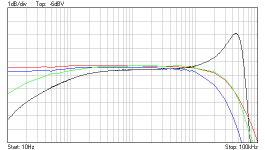
Red trace is with shunt feedback added and the gNFB through RC network.
The green trace is with shunt feedback and no gNFB.
If you compare it with the blue one, you'll notice the similarities and a little bell inside your head should begint to ring.
Now, how do i fix it ?
Red trace is with shunt feedback added and the gNFB through RC network.
The green trace is with shunt feedback and no gNFB.
If you compare it with the blue one, you'll notice the similarities and a little bell inside your head should begint to ring.
Now, how do i fix it ?
Attachments
Wow, it is starting to make sense..!
Red trace is with shunt feedback added and the gNFB through RC network.
The green trace is with shunt feedback and no gNFB.
If you compare it with the blue one, you'll notice the similarities and a little bell inside your head should begint to ring.
Now, how do i fix it ?
Dingdingding
OK, the OPT peaking is increasing the NFB at high frequency, causing less gain.
I'm guessing (without detailed observations) that the peaking is much greater on the primary side as the P-S coupling decreases, resulting in greater effect on the feedback vs. the output, hence the greater loss with local feedback.
This could be the issue Sheldon is noticing as well.
The feedback or the OPT or both could be compensated. I'd be inclined to try a zobel across the OPT primary as an experiment.
Great work!
Michael
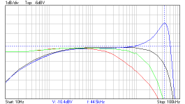
So.. I added a load of gNFB no RC network this time (altough turning it upside-down might have worked..)
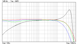
Black = open loop
Blue = with plate to plate feedback
Red = same as blue, but with gNFB
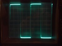
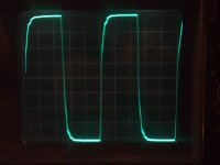
The other pics are square wave (1khz and 10khz) at 1 watt into the dummy load.
For the listening test.. I will need an additional gain stage!
Black = open loop
Blue = with plate to plate feedback
Red = same as blue, but with gNFB
The other pics are square wave (1khz and 10khz) at 1 watt into the dummy load.
For the listening test.. I will need an additional gain stage!
Attachments
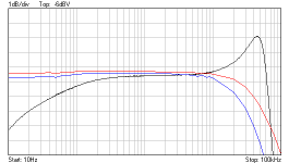
..So i replaced the 0.91µF capacitors I was using to couple the feedback resistors, with 47nF ones..
This creates LF roll-off in the feedback circuit, compensating the LF roll-off of the output Xformer..
(evil/genius plan, I leave it up to you to decide..)
Et voila!
No gNFB and pretty decent square wave response, even with a real speaker as load. Just like I wanted..
The green trace is that of the circuit I just described.
Attachments
The previous idea obviously was a stupid one, as it made the DF higher where you want it to be small, on the lower frequency's..
Another way, wich I'm testing now, is to make an arrangement with resistors, in baby huey style. And accross the resistor that connects the two phases together, I placed a zobel.
Now there is less damping in the highest frequency's, but the High frequency roll-off of the amplifier is much better then without the zobel..
The driver should be run at as high current where it has its sweet spot, check curves. Go for a D3a or E280F at 150V/150V/20mA. Also add gyrators instead of anode resistors. MJK has shown elsewhere how it should be done.
Hi Revintage
I have followed quite a lot of the recent discussions on gyrators, but can't remember about them being combined with pentodes. Can you please provide me with some further details, a link, or some keywords to search?
Thanks, Erik
- Status
- This old topic is closed. If you want to reopen this topic, contact a moderator using the "Report Post" button.
- Home
- Amplifiers
- Tubes / Valves
- plate to plate feedback - measurements