Attached is the first cut of a schematic for what I'm calling the "Iron Garter", incorporating a mosfet concertina splitter and source follower for the outputs, combined with Blumlein "Garter" compensation to help even out the bias current between the output tubes. I had tried adding garter compensation to my "No Light District Amp", but it was touchy/high gain with that particular circuit and and doubled the parts count. Here the compensation is more easily controlled, and with fewer parts. Since I have boards built up with all the mosfet bits, breadboarding should start on this amp shortly. I may change to an input tube with lower gain than the 6AM4, but I'm leaving it in for now.
Attachments
I count four caps (if count includes gates) and a transformer as possible
poles of phase shift in the feedback loop. Which one is the dominant, how
high did you set the -3db knee, and how high before +/-120 shift rolls in?
Since you have a loop, I'd be tempted to sacrifice splitter symmetry to
lose some of the gatecappage. What made you choose MOSFETs rather
than BJT for concertina and driver/followers? We seem already given up
linearity by allowing output Pentodes to operate with no local feedback
aside from the DC garter. So good function of the loop will be essential.
If all else being equal, and I'm not saying it is or ain't...
With BJT in those locations, you could ditch at least six Zeniers.
How many D14's you got in that schematic anyway?
D14's not even all the same type 1N4752 (neg rail) vs 1N5248 (gates)...
You got 50V OPT swing either way before screen currents begin to
begin to affect the quiescent bias of the garter. With the feedback
loop correcting crossing errors, that might be acceptable, but just
be aware of it. How fast do things return to smooth crossing after
a loud passage has dumped a lot of screen current?
I am really stretching here to find details I can nitpick. Its a good
first draft that would no doubt function as-is.
Last edited:
The feedback compensation cap is there as a placeholder until I see how the circuit really performs. In all the p-p circuits I've done, the transformer acts as dominant pole, actually rolling off signs of input/driver stage misbehavior so that I had to probe previous stages as well as the output to see what was really going on. There is no place for partial feedback here, unless one wants to do it right from plate to grid (or plate to follower) on the outputs. Having said that, I was just looking at on old copy of the ARRL handbook yesterday, where they show a capacitive divider used for "neutralization" (actually negative feedback) used on the final stage to quell oscillation. Food for thought, but only after I get the amp running in its current state.
The follower mosfets are selected for low gate charge and low input capacitance. The stage driving them is a triode with relatively low Rp. I don't anticipate any problems, and indeed have not had any with this arrangement in the past. The zeners are all the same type in the schematic (18V), except for the one regulating the negative bias(33V). They will not conduct unless the gate is overdriven. As for mosfets vs. BJTs, I don't like having to supply base current, or having to worry about recovery from saturation (perhaps a real concern in the case of the splitter). In the breadboard stage, I'll do a little tinkering with the input to provide maximum headroom for the splitter.
One interesting worry is how long it will take the cut-off follower to recover from a negative signal excursion. That's what square wave tests are for...
I went back last night and corrected the reference designators (and some values) to make everything line up nicely. I want to take a look at my notes at work to check on a few more values in the bias circuit, them I will post the revised schematic. The 6P14P data sheet claims that I need only around ~8V of negative bias for my planned quiescent current of ~30ma/tube. That's a pretty sensitive tube. We'll see what actually happens in the breadboard.
Miller cap from V1 plate to V1 grid. Neutralization cap from V2 plate to V1 grid.
Hopefully neutralizer cap is equal to Miller. Miller NFB + Neutralization PFB = 0.
Grid V1 in middle of this voltage divider sees only parallel caps to virtual GND.
I don't think Pentode Miller is significant at audio frequency compared to the
MOSFETs or even the Triode.
Hopefully neutralizer cap is equal to Miller. Miller NFB + Neutralization PFB = 0.
Grid V1 in middle of this voltage divider sees only parallel caps to virtual GND.
I don't think Pentode Miller is significant at audio frequency compared to the
MOSFETs or even the Triode.
Last edited:
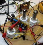
Neutralization or no, here's a pic of the first breadboard for the "Iron Garter". No smoke was released, but as I thought, I will need to tweak the bias current through the 6AM4 downward so that I can get a little headroom at the mosfet concertina. No snarky spurious oscilation was seen, so the last thing I'll do before I put the breadboard away and spend some effort on my "No Light" project is to take a clip lead and close the loop.
I'm using a Baldwin 6BQ5 P-P transformer in the breadboard because it was close at hand, and I would spend far less tears on it if I accidently zorched it for some reason. The new values I find will be included in the next schematic I post.
I'm using a Baldwin 6BQ5 P-P transformer in the breadboard because it was close at hand, and I would spend far less tears on it if I accidently zorched it for some reason. The new values I find will be included in the next schematic I post.
Attachments
Attached is the updated schematic for the Iron Garter, with changes to reduce current in the input tube to bring down the plate voltage a bit, and a change to a value in the output bias string. The breadboard functions well enough open loop that I want to put together a chassis with the Fisher X-100 output transformers before I start working really hard on the closed loop compensation. It oscillates closed-loop with the Baldwin output transformer, but there's no loop compensation cap in place. For once, this project came together without a lot of roaring and screaming and hair-tearing.
Attachments
The garter gets relaxed a bit for my first implementation of Blumlein garter bias, using a hybrid input stage with mosfet input and standard (plus garter) DC coupled folded cascode output drive.
Schematics may (or may not) follow when I get this puppy up and working with Scott output iron and unselected 6P14P-EV outputs.
Schematics may (or may not) follow when I get this puppy up and working with Scott output iron and unselected 6P14P-EV outputs.
I have used the same phase splitter in guitar amps with a 12AX7 (actually an 18FY6A in a series heater amp) tied to an LND150 and 100K resistors. It feeds the output tubes directly with no buffering. Some may not like this, but I think it sounds better than the 12AX7 it replaced.
You usually don't need two zeners on each mosfet. The gate doesn't need to go more than 0.7 volts negative on most mosfets to cut the fet off, so just use a single zener.
You usually don't need two zeners on each mosfet. The gate doesn't need to go more than 0.7 volts negative on most mosfets to cut the fet off, so just use a single zener.
The circuit I'm currently contemplating doesn't look at all like the current schematic, being DC coupled from the driver/splitter to the outputs, with Blumlein garter equalization and partial feedback (also full of nasty silicon). Traditionalists will probably be outraged, but that's their problem. They can continue to carve crude wheels out of stone just like grandpa if that's what gets them hot.
Traditionalists will probably be outraged
When I published the schematic of the TSE about 10 years ago the response was overwhelmingly negative. It uses a mosfet CCS loaded 5842 and a mosfet follower driving the grid of a DHT. Some even suggested that I change my name to Transistorlab!
Now that a few hundred people have built them, the tide is slowly changing.
They can continue to carve crude wheels out of stone just like grandpa
Hey, I resemble that remark (4 grandkids)......I just cooked up my first PC board in the backyard of the new place. It contains one sweep tube and 4 mosfets. It is a breadboard for experimental use, so all 4 mosfets will not be used simultaneously.......unless that wild idea just happens to work. There is a mosfet connected to each element of the tube except the plate.......
Wasn't even aimed in your general direction
I know, but there are always the stubborn few that can't stand the site of silicon in a tube amp even though they have never heard it themselves. The guitar amp guys are even more stubborn. The LND150 phase inverter really set a few of them off.
wrenchone, go for it.......I am happy to see a circuit design taking this direction.
Back in my car audio days I had the "opportunity" (said with all the sarcasm I can muster) to work with "BK Buttnerd" and his so called tube driver amps, unfortunately it was one of those experiences I could of done without as his design (at the time) was total BS. You could pull the tubes out and the amp still played, I don't think the LED heated the tubes enough to let them work....LOL, it was all smoke and mirrors.
But, the company I worked for back then allowed us to fix his BS and made it work very nicely......now he gets fame for other peoples work, hes like the Thomas Edison of car audio IMHO.
While I am now loving building tube amps and such, I can tell you this. Silicone can be made to sound as good as (if not better than) some of the best tube designs out there. While working for Xtant, our amplifiers could be "blind" switched on the same speakers with no between a High End tube amp, a high end Solid State (SS) amp. and our Car audio amp and the listeners would choose our fully MOSFET SS car amp 9 out of 10 times.
Its funny that I see interest in tube amps for cars here on this site lately too, I should dig up the power supply designs for them so they can get the high voltages and heater voltages they need to do it...............
Here is the preliminary circuit for the latest amp, with partial feedback and Blumlein "Garter" output bias compensation. I'll probably have to tweak some values to adjust the output bias, but what's there will do for starters. The nest of components at the bottom is a shunt regulator for the output bias.
I'm using the power transformer from a Fisher console, augmented with a little 7VA PCB mount transformer for the front end bias. Output iron is also vintage Fisher.
If I'm feeling industrious, I'll start drilling the holes for the top deck components today. The case is some sort of wall-mount enclosure for an alarm system or some such, cheap at $5 from a local surplus store. It's made out of sturdy steel, and is about the right size for a little amp like this. Some auto touch-up paint (metallic blue, with cast-iron grey for XFMRs) will dress it up considerably
Attachments
Go argue with this guy.
Blumlein’s Garter Circuit Revisited
Both variants shown here were inspired by the original circuit, one with the compensation placed ahead of followers to allow higher values in the compensation resistors, the other a stripped-down approach used with combination bias.
Blumlein’s Garter Circuit Revisited
Both variants shown here were inspired by the original circuit, one with the compensation placed ahead of followers to allow higher values in the compensation resistors, the other a stripped-down approach used with combination bias.
- Status
- This old topic is closed. If you want to reopen this topic, contact a moderator using the "Report Post" button.
- Home
- Amplifiers
- Tubes / Valves
- "Iron Garter" Push-Pull Amplifier