Hello,
I want to build amplifiers for mid & high frequency for my Linkwitz Orions. They are active speakers with an external line level crossover. The tweeter and midrange drivers are
Seas T25CF002 THE ART OF SOUND PERFECTION BY SEAS - E0011-06 T25CF002
and Seas W22EX001
THE ART OF SOUND PERFECTION BY SEAS - E0022-08S W22EX001
The sensitivity is 87-88 Db/1Wat so I will need all power that can be obtained from the output tube. The crossover points are 120 Hz & 1440 Hz. The crossover is Linkwitz-Riley 4th order. I want the amp driving the midrange to be a full range so I can use it to drive my second speakers. Due to the crossover point between the midrange and the tweeters I want the amps to be as similar as reasonable that is the same topology and the same tubes. I think the signal inductance and capacitance on the tweeter amps should be lowered. I would be grateful for the recommendations of the values or calculating formulas.
I don’t want to replace the speakers as I don’t believe that for a price affordable for me I can get speakers which are better for me. They satisfy me for the most parts, dynamic, soundstaging, listening at low or high level; I don’t get tired listening to them for a prolonged time. The only issue that I want to fix is some washing down of timbre in the midrange (I just want a little bit more of wood in the violin sound, etc). I do believe that the main (but not the only) culprit is my amplifier. It’s just a 12 channels AT-6012.
I do realize the complexity and the cost of such project. It will take for me probably more than a year from the first soldered joint. I do realize the danger of very high voltage exceeding 1KV.
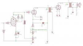
The approximate schematic I’m going to use is

It’s essentially a DRD cascade driving trough an interstage GM-70. I saw on this forum a little bit different implementation of DRD idea by Thorsten Loesch. It seems for me more elegant so I will probably use it with his permission.
I have some questions about A2 class and about GM-70 in A2. I found curves with positive grid lines at the end of
http://frank.pocnet.net/sheets/018/g/GM70.pdf
The question is do they look good enough (that is are they spaced evenly enough) so there is a sense to drive GM-70 into A2.
Another question is the ability of 300B to drive the grid of GM-70 via interstage not in terms of voltage but in terms of current. In Wikipedia
Single-ended triode - Wikipedia, the free encyclopedia
I read the following
Class A2
Class A2 amplifiers can overcome a high Rp by driving the grid positive with respect to the plate. Because this makes the grid a secondary anode, it too will draw current from the cathode while accelerating the remaining electrons towards the plate. Grid currents can place extreme demands on the driving circuitry, sometimes requiring as much as 8 watts input for larger tubes such as the 211.
If 211 requires 8 Watts of power for A2 than GM-70 may require even more. In this case 300B will not drive it from its anode even via an interstage transformer and I may probably have to replace the interstage by a choke and to drive the output via mosfet follower as in tubelab’s 845SE.
Another issue I read about is that an interstage transformer doesn’t like transition from A1 to A2. I don’t know if the issue is serious enough. I like interstage coupling as it simple enough and I would prefer not to increase the complexity unnecessarily.
For simplicity I want to use a solid state PSU. I have some question about capacitors. Is there available for a reasonable price high voltage non electrolytic capacitors with capacity of around 70uF and 2KV voltage? The size of the capacitor doesn’t bother me if doesn’t exceed the size of a brick too much.
Any critic and recommendations are welcome.
Thank you
Victor
I want to build amplifiers for mid & high frequency for my Linkwitz Orions. They are active speakers with an external line level crossover. The tweeter and midrange drivers are
Seas T25CF002 THE ART OF SOUND PERFECTION BY SEAS - E0011-06 T25CF002
and Seas W22EX001
THE ART OF SOUND PERFECTION BY SEAS - E0022-08S W22EX001
The sensitivity is 87-88 Db/1Wat so I will need all power that can be obtained from the output tube. The crossover points are 120 Hz & 1440 Hz. The crossover is Linkwitz-Riley 4th order. I want the amp driving the midrange to be a full range so I can use it to drive my second speakers. Due to the crossover point between the midrange and the tweeters I want the amps to be as similar as reasonable that is the same topology and the same tubes. I think the signal inductance and capacitance on the tweeter amps should be lowered. I would be grateful for the recommendations of the values or calculating formulas.
I don’t want to replace the speakers as I don’t believe that for a price affordable for me I can get speakers which are better for me. They satisfy me for the most parts, dynamic, soundstaging, listening at low or high level; I don’t get tired listening to them for a prolonged time. The only issue that I want to fix is some washing down of timbre in the midrange (I just want a little bit more of wood in the violin sound, etc). I do believe that the main (but not the only) culprit is my amplifier. It’s just a 12 channels AT-6012.
I do realize the complexity and the cost of such project. It will take for me probably more than a year from the first soldered joint. I do realize the danger of very high voltage exceeding 1KV.
The approximate schematic I’m going to use is
It’s essentially a DRD cascade driving trough an interstage GM-70. I saw on this forum a little bit different implementation of DRD idea by Thorsten Loesch. It seems for me more elegant so I will probably use it with his permission.
I have some questions about A2 class and about GM-70 in A2. I found curves with positive grid lines at the end of
http://frank.pocnet.net/sheets/018/g/GM70.pdf
The question is do they look good enough (that is are they spaced evenly enough) so there is a sense to drive GM-70 into A2.
Another question is the ability of 300B to drive the grid of GM-70 via interstage not in terms of voltage but in terms of current. In Wikipedia
Single-ended triode - Wikipedia, the free encyclopedia
I read the following
Class A2
Class A2 amplifiers can overcome a high Rp by driving the grid positive with respect to the plate. Because this makes the grid a secondary anode, it too will draw current from the cathode while accelerating the remaining electrons towards the plate. Grid currents can place extreme demands on the driving circuitry, sometimes requiring as much as 8 watts input for larger tubes such as the 211.
If 211 requires 8 Watts of power for A2 than GM-70 may require even more. In this case 300B will not drive it from its anode even via an interstage transformer and I may probably have to replace the interstage by a choke and to drive the output via mosfet follower as in tubelab’s 845SE.
Another issue I read about is that an interstage transformer doesn’t like transition from A1 to A2. I don’t know if the issue is serious enough. I like interstage coupling as it simple enough and I would prefer not to increase the complexity unnecessarily.
For simplicity I want to use a solid state PSU. I have some question about capacitors. Is there available for a reasonable price high voltage non electrolytic capacitors with capacity of around 70uF and 2KV voltage? The size of the capacitor doesn’t bother me if doesn’t exceed the size of a brick too much.
Any critic and recommendations are welcome.
Thank you
Victor
Attachments
Really Unbelievable text from Wikipedia !
Should be "....with respect to cathode"
The current flows completely opposite direction. From grid to cathode.
(electrons flow from cathode to grid, not the current)
Concerning your circuitry:
I do not see any reason that the output tube should be driven to positive grid voltage and thus to grid current.
Please let me know your point for this.
What output power you are aiming at ?
Class A2 amplifiers can overcome a high Rp by driving the grid positive with respect to the plate. Because this makes the grid a secondary anode, it too will draw current from the cathode while accelerating the remaining electrons towards the plate. Grid currents can place extreme demands on the driving circuitry, sometimes requiring as much as 8 watts input for larger tubes such as the 211.
Class A2 amplifiers can overcome a high Rp by driving the grid positive with respect to the plate.
Should be "....with respect to cathode"
...it too will draw current from the cathode
The current flows completely opposite direction. From grid to cathode.
(electrons flow from cathode to grid, not the current)
Concerning your circuitry:
I do not see any reason that the output tube should be driven to positive grid voltage and thus to grid current.
Please let me know your point for this.
What output power you are aiming at ?
I do not see any reason that the output tube should be driven to positive grid voltage and thus to grid current.
Please let me know your point for this.
What output power you are aiming at ?
In a class A1 with the load of 10K and plate dissipation 120 Watts I can probably get 35-36 Watts from the GM-70. Driving the grid 80V positive I will extract around 50 Watts. On my current schematic B+ and grid voltages are tentative. I calculated them for class A1 only.
I can't comment on the scheem as I leave that to others, but I am using Rod's DHT heater boards on my GM70 to ensure clean and pure DC going to the heaters. You might want to look at that as the hum coming from the 300B will get amplified. Rod sells them for the GM70 and 300B. Good luck
A2 in practice
Good morning Victor_2,
2 of my last amplifiers are using transmitting tubes and are driven in A2. Although i can not comment on the GM70 specifically in A2 you must drive the output device from a low impendance (enough milliamperes....). I think your 5K:5K interstage will seriously restrict your amplifier.
The larger amplifier i build (using 6SN7 - 300B - TB3/1000; all interstage coupled) i used a 4:1 stepdown interstage between the 300B to the TB3/1000 (comparable to the 833A).
The smaller amplifier uses a 6FJ7 to a 35TG. As there is not to much data available for these tubes in audio applications i had the interstage transformers wound as 1+1+1+1:1+1+1+1. So during the breadboarding/building i could find the optimum for driving the red hot output triodes. Again i found out that 4:1 was simply needed in this amp.
I found out this theory with this article of Stephane Puechmorel; maybe of interest for you too ?
http://membres.multimania.fr/puechmor/bias/node5.html
And his conclusion:
- Lowest possible driver impedance.
- Interstage transformer wired so that driver's plate current and grid current are in phase.
- Local feedback loop around driver and interstage transformer if needed
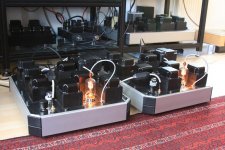
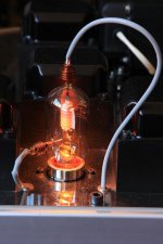
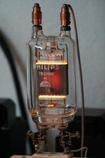
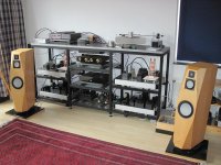
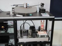
Included some pictures of the amplifiers (the TB3/1000 kicks out 70 Watts; the 35TG only 10 Watts).
Succes with the project !
Reinout
Good morning Victor_2,
2 of my last amplifiers are using transmitting tubes and are driven in A2. Although i can not comment on the GM70 specifically in A2 you must drive the output device from a low impendance (enough milliamperes....). I think your 5K:5K interstage will seriously restrict your amplifier.
The larger amplifier i build (using 6SN7 - 300B - TB3/1000; all interstage coupled) i used a 4:1 stepdown interstage between the 300B to the TB3/1000 (comparable to the 833A).
The smaller amplifier uses a 6FJ7 to a 35TG. As there is not to much data available for these tubes in audio applications i had the interstage transformers wound as 1+1+1+1:1+1+1+1. So during the breadboarding/building i could find the optimum for driving the red hot output triodes. Again i found out that 4:1 was simply needed in this amp.
I found out this theory with this article of Stephane Puechmorel; maybe of interest for you too ?
http://membres.multimania.fr/puechmor/bias/node5.html
And his conclusion:
- Lowest possible driver impedance.
- Interstage transformer wired so that driver's plate current and grid current are in phase.
- Local feedback loop around driver and interstage transformer if needed
Included some pictures of the amplifiers (the TB3/1000 kicks out 70 Watts; the 35TG only 10 Watts).
Succes with the project !
Reinout
Attachments
Driving the grid 80V positive I will extract around 50 Watts.
The bias voltage seems to be -120V. If the output tube stays in A1, Then the driving voltage can be some 0 to -240 V. This is clear as normal operating condition.
In case the driving voltage is increased so that the positive peaks go to + 80V, then the negative peaks must go -320 V. The total drive is 400 Vpp.
Are negative peaks now clipping due to anode current cut-off.
Is the tube anymore at linear operating region ?? I doubt it is not.
Thank you Reynout for the for the article on A2 operation and good wishes. Your amps really look nice.
To drive GM-70 into A2 i need voltage swing from +80V to -240V. That is 320V peek to peek. Now lets assume we are using a step-down interstage with 4:1 ratio. That means the stage driving the primary of the interstage must provide 1480V swing. With some reserve to lover the distortion this tube has to have 1000V on its anode. So it must be something like 211, 845, or another GM-70. In this case DRD doesn't have sense at all as the B+ for it will be even more than for GM-70. It means the topology of the amp has to change to something like this: High mu triode or triode-wired pentode choke loaded -> 212 or 845 or another GM:70 -> interstage 4:1 ->GM70. Scheme becomes way to complicated and expensive. And the heat generated by 8 transmitter tubes will be enormous.
So it leaves me with the following choices
1. Be content with something around 35 Watts of the output power and not leave class A1 operation.
2. Use a high current tube as 6C33C with a 1:1 interstage.
3. Use a high power cathode follower as a driving stage. At the current state it is far beyond my skills to design a good one for this purpose.
4. Use mosfet follower.
I have to think about it a little bit more. At the current moment choices 1 & 4 are most appealing to me.
If I use A2 operation with with maximum positive swing on the grid 80V the operating point of GM-70 will be changed to 920V on B+, and 80V on the grid.
Thanks everybody for the advises.
Victor.
To drive GM-70 into A2 i need voltage swing from +80V to -240V. That is 320V peek to peek. Now lets assume we are using a step-down interstage with 4:1 ratio. That means the stage driving the primary of the interstage must provide 1480V swing. With some reserve to lover the distortion this tube has to have 1000V on its anode. So it must be something like 211, 845, or another GM-70. In this case DRD doesn't have sense at all as the B+ for it will be even more than for GM-70. It means the topology of the amp has to change to something like this: High mu triode or triode-wired pentode choke loaded -> 212 or 845 or another GM:70 -> interstage 4:1 ->GM70. Scheme becomes way to complicated and expensive. And the heat generated by 8 transmitter tubes will be enormous.
So it leaves me with the following choices
1. Be content with something around 35 Watts of the output power and not leave class A1 operation.
2. Use a high current tube as 6C33C with a 1:1 interstage.
3. Use a high power cathode follower as a driving stage. At the current state it is far beyond my skills to design a good one for this purpose.
4. Use mosfet follower.
I have to think about it a little bit more. At the current moment choices 1 & 4 are most appealing to me.
The bias voltage seems to be -120V. If the output tube stays in A1, Then the driving voltage can be some 0 to -240 V. This is clear as normal operating condition.
In case the driving voltage is increased so that the positive peaks go to + 80V, then the negative peaks must go -320 V. The total drive is 400 Vpp.
Are negative peaks now clipping due to anode current cut-off.
Is the tube anymore at linear operating region ?? I doubt it is not.
If I use A2 operation with with maximum positive swing on the grid 80V the operating point of GM-70 will be changed to 920V on B+, and 80V on the grid.
Thanks everybody for the advises.
Victor.
Last edited:
I looked at the curves of GM-70 and observed some points:
In case you are going to bias the GM-70 with -120 V at the grid and 1200 V at the anode, the anode current seems to be 160 mA meaning anode dissipation of some 190 W. The manufacturer's recommended absolute maximum is 125 W. If you want to stay within recommended limit, the -Ug should be some -155 V corresponding to about 100...105 mA of anode current.
In case you will stay within normal operation (A1) and avoid going into grid current area. Then the expected output power, which can be estimated from max. anode dissipation, is probably 40 W minimum.
Typically these transmitter tubes are quite conventionally specified with respect to max. anode dissipation, and is quite likely that some 130...140 W is still in acceptable level and do not essentially shorten the lifetime of the tube.
In summary it is obvious that even at A1 class operation, you will get 40 ...50 W output power. The biggest advantage with A1 class is that your driver construction is very, very much easier to accomplish.
I think that some 6SN7 or similar as choke-coupled voltage amplifier would be sufficient to fully drive the GM-70 in class A1.
I looked at the curves of GM-70 and observed some points:
In case you are going to bias the GM-70 with -120 V at the grid and 1200 V at the anode, the anode current seems to be 160 mA meaning anode dissipation of some 190 W. The manufacturer's recommended absolute maximum is 125 W. If you want to stay within recommended limit, the -Ug should be some -155 V corresponding to about 100...105 mA of anode current.
The datasheets at
http://www.4tubes.com/DATASHEETS/SCANS-Original/F--G/GM70-4.pdf
shows that at B+ = 1200 and grid voltage 120 the current through GM-70 is around 100ma
shows that at B+ = 1200 and grid voltage 120 the current through GM-70 is around 100ma Today 03:48 PM
No, please see below from the same datasheet:
An externally hosted image should be here but it was not working when we last tested it.
No, please see below from the same datasheet:
It seems that curves in http://www.4tubes.com/DATASHEETS/SCANS-Original/F--G/GM70-4.pdf
and in
http://frank.pocnet.net/sheets/018/g/GM70.pdf
are a little bit different and I'm not sure which are correct.
- Status
- This old topic is closed. If you want to reopen this topic, contact a moderator using the "Report Post" button.
- Home
- Amplifiers
- Tubes / Valves
- GM-70, A2, biamping