Hi All,
Here is the fun weekend project for those who does not want to spend much money on exotic parts.
I would like to start with some design objectives and describe my rationale for this project.
1. minimum cost (ideally zero, if I could use parts from my junk box)
2. decent sound
3. ability to drive 30 ohm headphones (Audio Technical ATH-M50)
4. chance to experiment with autoformers (never tried them before).
5. simplicity (duh!)
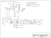
I selected Gary Dahl's Espressivo Headphone Amplifier as a prototype. It meets all objectives except the first one (low cost). The key components in Gary's amp are quite pricey, so I started to look at substitutions.
For an autoformer I selected the Sonance VC50B stereo volume control (there is also an in wall version VC60R). The unit contains two autoformers and 10-position attenuator switch. I bought it used on e-bay for $10.
I found 4 odd looking Soviet made 6Э5П (6JE5P or 6E5P ) tetrodes in my junk box. I remember pulling them from old oscilloscope when I was 12 and now they are getting a second life in US after 30 years") These tetrodes are quite remarkable in triode mode (high gm, low Rp).
These tetrodes are quite remarkable in triode mode (high gm, low Rp).
I used Gary Pimm's CCS as plate loads (I already had couple assembled and never used from previous project).
One more change from the prototype. I used diodes to bias tubes. Gary uses resistor bypassed by a cap. Again, I just wanted to experiment and try something different. I did not use LEDs because I could not find any which can sink 30 ma safely without paralleling and I had tons of 1N4148s.
The schematics is attached below. I will post construction pics shortly.
Here is the fun weekend project for those who does not want to spend much money on exotic parts.
I would like to start with some design objectives and describe my rationale for this project.
1. minimum cost (ideally zero, if I could use parts from my junk box)
2. decent sound
3. ability to drive 30 ohm headphones (Audio Technical ATH-M50)
4. chance to experiment with autoformers (never tried them before).
5. simplicity (duh!)
I selected Gary Dahl's Espressivo Headphone Amplifier as a prototype. It meets all objectives except the first one (low cost). The key components in Gary's amp are quite pricey, so I started to look at substitutions.
For an autoformer I selected the Sonance VC50B stereo volume control (there is also an in wall version VC60R). The unit contains two autoformers and 10-position attenuator switch. I bought it used on e-bay for $10.
I found 4 odd looking Soviet made 6Э5П (6JE5P or 6E5P ) tetrodes in my junk box. I remember pulling them from old oscilloscope when I was 12 and now they are getting a second life in US after 30 years
These tetrodes are quite remarkable in triode mode (high gm, low Rp).I used Gary Pimm's CCS as plate loads (I already had couple assembled and never used from previous project).
One more change from the prototype. I used diodes to bias tubes. Gary uses resistor bypassed by a cap. Again, I just wanted to experiment and try something different. I did not use LEDs because I could not find any which can sink 30 ma safely without paralleling and I had tons of 1N4148s.
The schematics is attached below. I will post construction pics shortly.
Attachments
Nice build!
How'z it sound...?
Btw. I guess you know this site... dsavitsk did several Espressivo "interpretations".
http://http://www.ecp.cc/less-pressivo.html
How'z it sound...?
Btw. I guess you know this site... dsavitsk did several Espressivo "interpretations".
http://http://www.ecp.cc/less-pressivo.html
Nice build!
How'z it sound...?
It Sounds very nice. I even did some initial measurements. -3db bandwith is 35 Hz-300kHz. I can see distorted waveform at very low frequencies, but that is expected.
The funny thing is that when I tell myself that I do not care much about how the final product comes out and take it easy, it always comes out nice
BTW. I guess you know this site... dsavitsk did several Espressivo "interpretations".
http://http://www.ecp.cc/less-pressivo.html
Thanks for the info. I was not aware of this. BTW, link is not working, but I will try the search.
nice! Wish we had access to reasonable cheap iron down here...
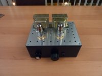
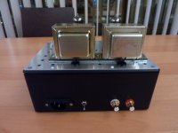
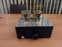
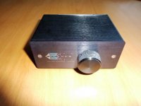
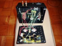
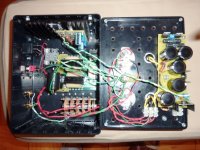
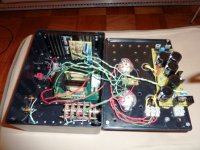
Thanks a lot. Again, I was not shooting for nice look. As you can see I used $5 Radio Shack plastic case (aluminum top plate is included) and Radio Shack power transformers $11 each.
Last edited:
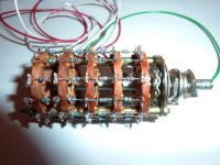
Here are some more pictures of the parts I used. First two are that of Sonance VC50B volume control with autoformers and switch. You can use the whole assembly as is with no modification.
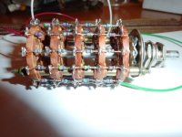
The next set is the input attenuator pictures. Of course the volume pot is easier solution, but I had this 5 deck switch lying around and I wanted to use it.
Last picture is assembled Gary Pimm CCS on heatsink.
The next set is the input attenuator pictures. Of course the volume pot is easier solution, but I had this 5 deck switch lying around and I wanted to use it.
Last picture is assembled Gary Pimm CCS on heatsink.
Attachments
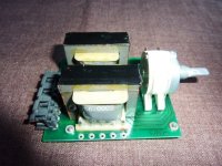
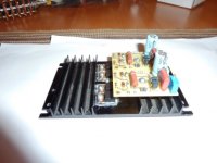
Here are some more pictures of the parts I used. First two are that of Sonance VC50B volume control with autoformers and switch. You can use the whole assembly as is with no modification.
The next set is the input attenuator pictures. Of course the volume pot is easier solution, but I had this 5 deck switch lying around and I wanted to use it.
Last picture is assembled Gary Pimm CCS on heatsink.
Beautiful!!!b Thank you.
Try here:
ecp.cc
Thanks. it worked now.
So do you just adjust the autoformer until it sounds good?
I am using autoformer on the lowest setting (maximum turns ratio). The gain is enough for the sources I am using. In this position the tube load (and distortion) is minimal.
First 4 settings are fine and then I can see distortion on the scope. Also, gain starts to level and then falls which means that the tube load gets heavy.
This tests were done with 33 ohm dummy load (to simulate my headphones).
With autotransformer the circuit is in principle a parallel feed type.
It's output voltage swing is only half compared to the ordinary transformer output stage. Thus it is presumable that the distortion is higher with your circuit at used level as well.
There is easy correction available to this. Since there is obviously more gain than is needed, consider to add some negative feedback into the circuit.
Then the frequency response and the linearity will be improved (distortion reduced). At the same time the gain can be adjusted to actual need.
(some 10 to 14 dB ?)
It's output voltage swing is only half compared to the ordinary transformer output stage. Thus it is presumable that the distortion is higher with your circuit at used level as well.
-3db bandwith is 35 Hz-300kHz. I can see distorted waveform at very low frequencies
There is easy correction available to this. Since there is obviously more gain than is needed, consider to add some negative feedback into the circuit.
Then the frequency response and the linearity will be improved (distortion reduced). At the same time the gain can be adjusted to actual need.
(some 10 to 14 dB ?)
I am using autoformer setting second from the bottom on the circuit diagram (light load for a tube, but high turns ratio). at this setting the voltage gain is around 1.3 or 1.1db. The next setting has voltage gain of 3db. I do not have any margin for voltage feedback at all.
Hi Guys,
I have a quick question, please let me know if you have an answer.
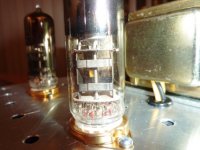
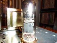
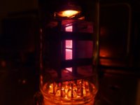
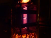
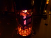
I took pictures of 6e5p tetrode connected as a triode (g2 connected to anode through 100ohm resistor).
I cant figure what is glowing, is this heater or g2 (see pictures) and is this normal?
Power dissipated on G2 is around 0.8W (2.3W max spec).
Pa is around 3.5W.
The rosy color on the pictures is a camera artifact, true color is dull red.
thanks, irakli
I have a quick question, please let me know if you have an answer.
I took pictures of 6e5p tetrode connected as a triode (g2 connected to anode through 100ohm resistor).
I cant figure what is glowing, is this heater or g2 (see pictures) and is this normal?
Power dissipated on G2 is around 0.8W (2.3W max spec).
Pa is around 3.5W.
The rosy color on the pictures is a camera artifact, true color is dull red.
thanks, irakli
Attachments
- Status
- This old topic is closed. If you want to reopen this topic, contact a moderator using the "Report Post" button.
- Home
- Amplifiers
- Tubes / Valves
- Espressivo Headphone Amplifier on Budget