I've tried searching on everything I can think of, but no luck finding an unusual schematic, that I recall being posted here back in Spring or early Summer. (I think it was P-P) Any help much appreciated.
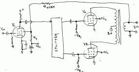
I recall someone was asking for opinions on some schematics to build and someone later posted a schematic where the global (or Schade maybe?) feedback was taken back to the screen grid (g2) of the 1st input gain tube (a pentode obviously, and there was no bypass cap from g2 to cathode either) . This unusual setup was not well reviewed at the time, not being the optimum in linearity compared to the usual cathode FDBK insertion.
I would like to find the original WWW source as well, since I would hope to hear some opinion(s) on how it sounded. Seems like a simple enough way to get a bit of SE "signature" for a class AB P-P amplifier with FDBK (and low output Z too). Combined with a few other techniques, it might do fairly well at SE emulation. (the "anti-triode" schemes, much discussed previously, are more or less limited to class A emulations or internal driver stages)
Thanks
Don
Last edited:
Umm, nope. Thanks anyway. I'm fairly sure it was posted sometime in the Spring/Early-Summer of 2010. Was actually a rather conventional looking schematic, except for the placement of the global feedback, ie., back to the input pentode's screen grid instead of the usual cathode resistor connection. See attached.
Edit: OOPs, just noticed that the Rfdbk would need a cap in series to prevent DC Rfdbk from dragging down the screen voltage. Well, you get the idea.
Someone was looking for a schematic to build, and this was one of the ones posted. Then maybe someone thought there was an error in it's feedback connection, and someone else maybe commented that it was just a sub-optimal linear feedback arrangement. (Well it would be sub-optimal for strict linearity, but this would instead give the amplifier some SE signature.)
Attachments
Last edited:
I can not help you to find the thread, but I have some doubts that this arrangement will give much SE sound. I think increased higher order harmonics is more likely.
For just a little bit of SE, maybe leave the first tube out of the feedback loop, and take the feedback to the phase splitter (grid of LTP second tube half).
Svein.
For just a little bit of SE, maybe leave the first tube out of the feedback loop, and take the feedback to the phase splitter (grid of LTP second tube half).
Svein.
RE:
"For just a little bit of SE, maybe leave the first tube out of the feedback loop, and take the feedback to the phase splitter (grid of LTP second tube half)."
Yes, I've seen that done, and that would be the more straightforward way of course. Letting the first tube give some open loop character to the transfer.
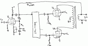
But with the small signal on the first gain tube here, V1, the plate voltage swing should be able to stay well above the screen voltage, and so avoid the usual screen current distortions seen in UL output stages. I've tested similar configurations of a pentode with a Mosfet follower off of its plate, and the Mosfet's source level shifted back to the pentode's screen grid for feedback. I've been able to get -60 dB distortion that way, mostly 2nd H (using a CCS load on the pentode). So I think this is workable. Especially if further gain follows the input tube in the amplifier to keep input level low. The SE signature strength can then be adjusted by variable plate loading of the input pentode. This approach would have some advantage in using the full open loop gain to lower the output Zo, while still delivering a SE signature.
I would probably further embellish the design with a triode/anti-triode P-P driver/splitter stage, to make the forward transfer SE'ish too. That way tracking SE forward path and backward (fdbk).
edit, Attached:
fixed the diagram (a cap in series with Rfdbk for DC isolation, although there are probably better ways to do that for fdbk stability, maybe use a zener with a cap across it instead)
Attachments
Last edited:
Hmm, I hadn't seen that one before. Direct coupled no less. Not the one I was looking for, since it had a single input pentode with screen feedback, which would be necessary to get the SE effects.
Nevertheless, interesting. Have you built it or something similar? You might want to do a Google search for Bill Perkin's SC 280.1 Power Amplifier, using balanced screen feedbacks, from around 1994. It used a McIntosh like output stage & OT, several KT90 tubes in parallel, and two 6AU6 input pentodes. Feedbacks to the 6AU6 screens came from a balanced (CT) secondary or optionally an extra feedback winding on the OT. Your Circlotron-like output would be more practical I think.
Nevertheless, interesting. Have you built it or something similar? You might want to do a Google search for Bill Perkin's SC 280.1 Power Amplifier, using balanced screen feedbacks, from around 1994. It used a McIntosh like output stage & OT, several KT90 tubes in parallel, and two 6AU6 input pentodes. Feedbacks to the 6AU6 screens came from a balanced (CT) secondary or optionally an extra feedback winding on the OT. Your Circlotron-like output would be more practical I think.
RCA RC-30 page 695 would be the conventional version, exactly.
It's got the usual global feedback to the input pentode cathode. Just would take moving the global over to the screen grid and reworking the feedback resistors, plus some DC offset allowance for Screen +V tie-in.
I'm just hoping the original WWW schematic source might have some comments on the resultant "sound" of such a setup. If I can't find it, I'll just try it out.
- Status
- This old topic is closed. If you want to reopen this topic, contact a moderator using the "Report Post" button.
- Home
- Amplifiers
- Tubes / Valves
- Trying to find an unusual schematic posted here this Spring

