I've been working on a 6D22S-rectified PS (for a 6C33C PP) in PSUDII for a couple of weeks, and have managed to get the voltage ripple down to ~1.6mV, but not lower (at least not without voltage and current warnings). Is this generally considered "acceptable", or should I continue working on it? I've been beating my head against a wall trying to get it flat - then realized that it would be a good idea to ask here before putting any more time into this...
This is my first attempt at designing a PS from scratch; I'd like to get it right.
Thanks, folks.
This is my first attempt at designing a PS from scratch; I'd like to get it right.
Thanks, folks.
Hello Guiseppe,
Tell us more!
What do you have going; capacitor, resistor, choke? Go too far past a Pi filter and start adding much resistance you get better ripple rejection at the expense of greater total impedance. Your power supply starts getting soft and acts like an unknown plate resistor.
DT
All just for Fun!
Ripple is better expressed relative to supply voltage then it can be related to the supply rejection of the amplifier that it is powering. Assuming a 400V supply the ripple is -108 db With an amplifier of 60db or better supply rejection I would be quite happy with a full load ripple of -40db as this would give 100db or better signal to ripple at full power. Your application may differ so it pays to define your goals everything is a compromise.
DT:
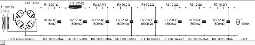
Schem attached. Couple of notes: R1 is a NTC thermistor (R at 25ºC=200Ω; R at Current=5.001Ω; max current 500mA); I'd prefer to have it on the 0V leg (per advice received here), but PSUD won't allow it. Choke is a Hammond 193N (3H, 500mA). The power trafo is 350V/500mA. The PS will be supplying one 6C33C at 200-225V, 400mA max.
Not sure if this is gonna work or not. I'm concerned about the max current at the choke. Any thoughts?
Sy: Still working on the amplifier design. At this point, all I know is 6N1P-EV input/6N6P drivers/6C33C-B outputs in PP.
I started playing with PSUD, and couldn't let it go...
Thanks for the responses. Everything I've read says work backwards from the OPT - I need to listen, and get the amp designed.
Guess I'm putting the cart before the horse... but PSUD is fun to work with.
Attachments
At this point, all I know is 6N1P-EV input/6N6P drivers/6C33C-B outputs in PP.
I started playing with PSUD, and couldn't let it go...
Thanks for the responses. Everything I've read says work backwards from the OPT - I need to listen, and get the amp designed.
Well, this will be much easier than you think. It's a power amp, so voltage levels are pretty high. It's push-pull so there's ripple cancellation there, too. I think it will be difficult to screw this up.
The main things to be concerned about are keeping the ripple current reasonably low (don't use a monster cap at the input of the filter) and the way you actually do the grounding (don't induce ripple currents into the grounds). Past that, it's pretty simple. Don't get carried away!
Try switching C1 to around 40uF and let us know the results.
IFRM hits 1.8A. Max for that bridge is 1.0A, so this is not good.
Ripple IS reduced to ~0.3mV, though...
Last edited:
Sy:
Thank you, sir.
I take it C1 at 0.47uF does NOT qualify as a Monster Cap?
Quick question: Can I use the thermistor in the R1 position shown on my schem, or should I move it to the 0V leg? Does it really make any difference? I haven't tried to run the circuit without R1 - need to see what happens with that gone...
Thank you, sir.
...don't use a monster cap at the input of the filter...
I take it C1 at 0.47uF does NOT qualify as a Monster Cap?
Quick question: Can I use the thermistor in the R1 position shown on my schem, or should I move it to the 0V leg? Does it really make any difference? I haven't tried to run the circuit without R1 - need to see what happens with that gone...
Why not put the thermistor in the primary?
Why not simplify things and parallel all of those caps, with an appropriate dropping resistor for your target voltage?
Limitations of PSUDII; neither configuration is allowed by the program. As I don't have the EE chops to do this on my own, I gotta play in PSUD's sandbox, by its rules...
I like both ideas - although I have a question: What effect (if any) will running all the caps in parallel w/o resistors (except for the one "bulk" dropping resistor) have on the circuit, esp. noise reduction. If I'm understanding this correctly, I'd be trading a load of Pi filters for some simplicity - what would I lose?
Sy: So place the thermistor in series between the mains and the primary side of the power trafo? Anything to worry about besides the usual trafo voltage/current draw? What R values (both ends) should I shoot for?
Thanks, folks - I appreciate all the help.
I like both ideas - although I have a question: What effect (if any) will running all the caps in parallel w/o resistors (except for the one "bulk" dropping resistor) have on the circuit, esp. noise reduction. If I'm understanding this correctly, I'd be trading a load of Pi filters for some simplicity - what would I lose?
You could split the parallel caps into two groups ...or three -- I was just pointing out the basic inefficiency of your proposal. Also, given that this circuit is push pull, I doubt that you'd need so much filtering. If your circuit is decently balanced, grounding problems (and other gremlins) would be more apt to create noise than a nominal PSU. I've heard quiet PP amps that had a grand total of 150uF in the PSU.
It looks like a choke input filter PSU the 0.47uf capacitor is token. What is the load regulation like? supplying a PP amplifier the load will vary, Find out the the quiescent and peak current of the amplifier? then check the power supply output voltage at these limits. You will probably find that load induced ripple is many times the mains induced ripple and that the design might benefit from less filter stages and a larger final filter capacitor. Modern capacitors are so small physically there is no reason to use so many 200uF capacitors if fewer larger ones will give a similar or better result for example a 1967 vintage 200uF 325V can electrolytic was around 38mm x 100mm, a modern 470uF 450V snap in capacitor is around 38mm x 50mm.
So place the thermistor in series between the mains and the primary side of the power trafo? Anything to worry about besides the usual trafo voltage/current draw? What R values (both ends) should I shoot for?
You got it.
You can include the effects of the primary-connected thermistor in PSUD by using the "hot" resistance as part of the primary resistance in the transformer calculator. The simulated voltage rise during warmup will be distorted since it won't account for the cold resistance and the time-dependent change to the hot resistance, but PSUD isn't really accurate about that anyway. You will still get accurate numbers for the "warmed-up" voltages and currents.
Provided your output stage and phase splitter are reasonably well balanced you can get away with quite a lot of HT ripple at the output stage. Just make sure earlier stages are well decoupled, as they need smooth HT.
Ball park calculation: assume 200V anode swing, then -80dB hum means 20mV ripple, but then assume 10% balance to get an extra -20dB cancellation so ripple can be 200mV.
For my modified 5-20 I just use a single 250uF reservoir cap, fed from a bridge rectifier with 22ohms in series. Calculated ripple is 4V peak! This feeds the output; earlier stages have extra smoothing. Hum is inaudible, but I do have about 20dB of feedback too so this is consistent with my ball park calculation. You can adjust the numbers to suit your own situation.
- Status
- This old topic is closed. If you want to reopen this topic, contact a moderator using the "Report Post" button.
- Home
- Amplifiers
- Power Supplies
- Tube PS question: Acceptable ripple