Hi Thomas,
Well, the 6n7gt (specially the blackened one) is not that available, haven't tried the metal version though. Either way, I have 6sl7, 6sn7, 6j5 and 6f8 in stock that I could use, so won't we looking at buying additional valves. I was keen on using the 2,5v triode in order to simplify the filament circuit
Cheers,
Ale
Hi Anton,
I will start construction of the 26/45 amp in January. It is for a customer who ordered such an amp. It will actually have the output tube switchable between 45 and 2A3. Input tube wil be switchable between 26 and 10Y.
Input tube will be transformercoupled with Tango NC20. Outptut transformer is Tango XE20.
Such a configuration will have quite low gain. You need to determine your gain requirements. Depends on the preamp. In my case the amp will be used as a midrange/tweeter amp in a two way active system. Here the amp will drive a horn which has much higher sensitivity than the bass. So this matches well.
You might need to use a step up input transformer to get enough gain. In that case you need to make sure your preamp can drive it.
Best regards
Thomas
Hi Thomas,
Thanks FYI.
This is my first time building a tube amp actually,
my plan is the 26/45 to be used as a full-range amp to drive Fostex,
and it will be an integrated amp (no Pre-amp).
Do think I can use such config for Fostex FR speaker?
and how much gain is actually need it?
Cheers....
Anton
Thanks FYI.
This is my first time building a tube amp actually,
my plan is the 26/45 to be used as a full-range amp to drive Fostex,
and it will be an integrated amp (no Pre-amp).
Do think I can use such config for Fostex FR speaker?
and how much gain is actually need it?
Cheers....
Anton
not enuff gain
Hi Anton
I breadboarded a 26 direct coupled 45 amp. Not enough gain on my Coral Beta 8 (~100db/m). Probably need a 1:4 or greater input transformer. You won't get enough gain with a Fostex.
Cheers
Vincent
Hi Thomas,
Thanks for your explanation, so, I'll have to find replacement driver then.
the reason why I'm building 26/45, because I have those tubes already.
Cheers...
Anton
Hi Anton
I breadboarded a 26 direct coupled 45 amp. Not enough gain on my Coral Beta 8 (~100db/m). Probably need a 1:4 or greater input transformer. You won't get enough gain with a Fostex.
An externally hosted image should be here but it was not working when we last tested it.
Cheers
Vincent
6SL7 driver for 45 SET
Hi everyone,
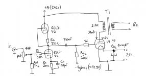
I'm planning to build a 45 SET intended to drive my GRADO headphones or alternatively small speakers with power being less than 1W. I've played with tubecad and managed to arrive at the attached design.
Driver circuit is 6SL7 in SRPP with a gain of 37 (31dB) approx. The 45 output valve is operated at 34mA and a bias of -42.2V and plate of 238V. This yields less than 1% of THD when 200mW are delivered and grid peak to peak is 15V. It can also deliver roughly 800mW when driver grid gets to 30Vpp. THD is slightly over 4% then.
Any suggestions for improvements?
I think I need to elevate the heater supply of V2, which would be a pain in the back. Is this really needed? Do I need separate 6.3V supplies to elevate only V2 heater circuit?
Thanks for the help!
Ale
Hi everyone,
I'm planning to build a 45 SET intended to drive my GRADO headphones or alternatively small speakers with power being less than 1W. I've played with tubecad and managed to arrive at the attached design.
Driver circuit is 6SL7 in SRPP with a gain of 37 (31dB) approx. The 45 output valve is operated at 34mA and a bias of -42.2V and plate of 238V. This yields less than 1% of THD when 200mW are delivered and grid peak to peak is 15V. It can also deliver roughly 800mW when driver grid gets to 30Vpp. THD is slightly over 4% then.
Any suggestions for improvements?
I think I need to elevate the heater supply of V2, which would be a pain in the back. Is this really needed? Do I need separate 6.3V supplies to elevate only V2 heater circuit?
Thanks for the help!
Ale
Attachments
Hi everyone,
I'm planning to build a 45 SET intended to drive my GRADO headphones or alternatively small speakers with power being less than 1W. I've played with tubecad and managed to arrive at the attached design.
Driver circuit is 6SL7 in SRPP with a gain of 37 (31dB) approx. The 45 output valve is operated at 34mA and a bias of -42.2V and plate of 238V. This yields less than 1% of THD when 200mW are delivered and grid peak to peak is 15V. It can also deliver roughly 800mW when driver grid gets to 30Vpp. THD is slightly over 4% then.
Any suggestions for improvements?
I think I need to elevate the heater supply of V2, which would be a pain in the back. Is this really needed? Do I need separate 6.3V supplies to elevate only V2 heater circuit?
Thanks for the help!
Ale
Driver actually isn't SRPP as connected, but mediocre current source loaded common cathode stage.. I think the cathode bias resistors in your SRPP are rather low in value, and I've found the 6SL7 to work best at currents of 2mA or less.. I'd recommend 820 - 1K resistors instead and I'd use it as an SRPP... The cathode bypass cap is a bit on the small side. A red led for bias on the bottom tube cathode and a 1K resistor in the top might make an interesting experiment.. (Section to section match could be an issue, and voltage will not divide evenly between the upper and lower sections of the SRPP - whether or not this is an issue depends on how extreme the imbalance is.)
Elevating the filament supply is really easy, it just takes 2 resistors and a cap and can be fed by your B+.. I would aim for more like 250V B+ and note that you can easily get 2Wrms out of this design with a 5K transformer, and that generally will translate into even better linearity at low levels than your current design. (4% thd at 2W is attainable with this tube.)
I strongly favor fixed bias and your OP is in the right range..
Last edited:
Hi Kevin,
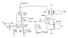
Thanks for the feedback. I actually made a mistake at drawing the circuit. It's a symmetrical SRPP. See ammended circuit attached.
I will rework the design to get 2ma and 1K resistors as per your suggestions. May also increase cathode cap....
Will also move B +250V and see what simulations I can get with a primary winding of 5K. Actually the transformer I have has 2.4K and 5K primary windings")
Question, if I elevate heater supply for the v2, am I not doing the same for V1? Shouldn't I have two separate 6.3v heater supplies to avoid this?
Thanks for the help.
Cheers,
ale
Thanks for the feedback. I actually made a mistake at drawing the circuit. It's a symmetrical SRPP. See ammended circuit attached.
I will rework the design to get 2ma and 1K resistors as per your suggestions. May also increase cathode cap....
Will also move B +250V and see what simulations I can get with a primary winding of 5K. Actually the transformer I have has 2.4K and 5K primary windings
Question, if I elevate heater supply for the v2, am I not doing the same for V1? Shouldn't I have two separate 6.3v heater supplies to avoid this?
Thanks for the help.
Cheers,
ale
Attachments
Question, if I elevate heater supply for the v2, am I not doing the same for V1? Shouldn't I have two separate 6.3v heater supplies to avoid this?
Split the difference in voltage at the cathode, and elevate the heater to that point. Noise reduction is almost as good with the heater below the potential of the cathode as it is above it.
On another note, here's another design you might want to consider. It uses the same tubes but with direct connection and some very clever noise cancelling, even with small supply caps. I made an 801 amp that I use for headphones (AKG 701). It's very quiet and sounds great. Here's the thread: http://www.diyaudio.com/forums/tubes-valves/125488-loftin-white-801-amp.html
I made up several other schemas for other tubes. Here's one for a 2A3. Just change the cathode resistor for the 45 and you're good to go. The resistors for the noise nulling circuit might need some adjustment. If you are interested, I'll recalculate.
Sheldon
Attachments
Last edited:
Hi Ale,
I think your circuit is unnecessarily complex. I don't see any advantage of the SRPP. It only brings problems with kathode-heater voltage differences and the need to elevate heaters. I played around with SRPP and mu followers a long time ago but dismissed them. I prefer transformercoupling, or if on a budget plain RC coupling.
I have mentioned in another thread that I think the 6SL7 is not well suited as a driver. if you insist on it, parallel both sections and run it RC coupled. Better choice is trhe 6N7 as mentioned by me earlier in this thread.
If you have the possibility for higher B+, use cathode bias on the 45. Way simpled than fixed bias.
Other points:
Why the huge grid stop resistor on the 6SL7? I've never experienced oscillations with the 6SL7, no grid resistor needed at all. Also the 45 will run fine without the grid stop resistor.
Best regards
Thomas
I'm considering a #26-45 pream/headphone amp, so I can get way with less gain. What I have never seen is a 45 SET with anything but a big ugly bypass cap. I am thinking of using the SSHV reg to deliver +145V to the cathode of the 45 and Dc couple to the 26 (~100V at its plate). The only cap would be an input coupling cap so I can apply neg battery bias to the #26 grid.
Curious if anyone has tried building a 45SET in such a manner or have any other schemes to eliminate the big cathode bypass cap under the 45.
Curious if anyone has tried building a 45SET in such a manner or have any other schemes to eliminate the big cathode bypass cap under the 45.
Hi regal,
even in DC coupled circuits there are often several caps 'hiding' somewhere which are still in the signal path. B+ caps, cap in the output of your regs, caps in the neg bias supplies, etc.
I commonly use the 'ultrapath' scheme in allmost all of my amps. This applies a cap from the B+ side of the output transformer primary to the cathode. This cap 'bypasses' the cathode resistor and it's bypass cap. Depending on the circuits, often the cathode bypass cap can be left out in this scheme.
Here is a circuit which illustrates this:
ImageShack® - Online Photo and Video Hosting
I'm using this scheme in my 45 amps too. There I can leave out the bypass cap. Ultrapath cap is a 30uF oil type. The cap is connected from B+ to the center tap of the filament winding. Sounds wonderful.
Best regards
Thomas
Hi regal,
even in DC coupled circuits there are often several caps 'hiding' somewhere which are still in the signal path. B+ caps, cap in the output of your regs, caps in the neg bias supplies, etc.
I commonly use the 'ultrapath' scheme in allmost all of my amps. This applies a cap from the B+ side of the output transformer primary to the cathode. This cap 'bypasses' the cathode resistor and it's bypass cap. Depending on the circuits, often the cathode bypass cap can be left out in this scheme.
Here is a circuit which illustrates this:
ImageShack® - Online Photo and Video Hosting
I'm using this scheme in my 45 amps too. There I can leave out the bypass cap. Ultrapath cap is a 30uF oil type. The cap is connected from B+ to the center tap of the filament winding. Sounds wonderful.
Best regards
Thomas
Thanks I'll put the ultrapath on my list of possibilities. The beautiful thing about a headphone SET amp powered by the SSHV reg is there really aren't any hidden large caps in the signal path. Of course this amp would be pushing the limits of this reg a bit, I guess you do explain why no one bothers to build a cathode bias power supply for a speaker amp as the ultrapath makes good sense with a typical speaker amp PS.
Really with good heatsinking it isn't out of the question that the SSHV could power a speaker 45 SET.
- Status
- This old topic is closed. If you want to reopen this topic, contact a moderator using the "Report Post" button.
- Home
- Amplifiers
- Tubes / Valves
- Back at the 45 SET