For those who like anode C.C.Sources and are restricted by the MJE350 at 300V max; Farnell have new H.V PNP additions PBHV9040Z & PBHV9540Z
stock no's 1829323 & 1829317 which open a 450V or higher range possibility.
The lower current version has a considerably lower collector capacitance than the MJE350.
Both these new issues being surface mount, the lower current capability for tube working isn't an issue but for high voltage, dissipation by V*/R heatsinking on a tab is necessary.
richy
With a little ingenuity, it is possible to use NPNs in role: here is an example of "unisex" circuit:
http://www.diyaudio.com/forums/solid-state/173005-improved-current-source-sink.html#post2294196
http://www.diyaudio.com/forums/solid-state/173005-improved-current-source-sink.html#post2294196
Elvee, I tried these types of circuit some time ago and with high gm tubes config as triodes the CCS oscillated as there is a macho gain conflict with rising frequency. I didn't want to damp the CCS to create stability, this defeating the purpose of wide bandwidth at very low distortion. The simplest circuit as shown in MJ's book I find works the best and is inherently stable.
More anon
richy
More anon
richy
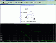
No, it isn't. It is caused by the collector capacitance of Q1 and the high output resistance: 5pF x 4.5Meg.Impedance starts dropping off at 10 kHz ?
That's not very impressive for a CCS, especially when modeling often looks better than the real thing.
Some improvement is possible by cascoding.
Many other CCS configurations also have several pF output capacitance, including the PNP ones.
Active cancellation in a similar way as for output resistance is in theory possible, but it is a slippery slope.
This illustrates what I said above.
Obviously, better results could be achieved by means of active cancellation techniques, but many plain vanilla CCS's will have an output capacitance larger than 4pF.
The apparently poor frequency performance is caused by the good performance of the compensation.
If you examine the absolute value of the impedance at a given frequency rather than the variation wrt frequency, you come to the conclusion that the circuit is not that bad after all.
Attachments
This illustrates what I said above.
Obviously, better results could be achieved by means of active cancellation techniques, but many plain vanilla CCS's will have an output capacitance larger than 4pF.
The overlooked bug is often the device mounted on a heatsink with a thin mica washer or sil impregated wafer where heatsink to substate capacitance may exceed 15-20pF. This makes the internal collector capacitance look small. Using a double alumina type insulator this tab to sink capacitance can easily be halved i.e around 7pF. Obviously the smaller capacitance the better. Beware using the emitter, this often has an even higher capacitance !
Also, I often use video pentodes as triodes with a CCS in the anode. The reason is obvious. The effective int Ra of the triode config is way lower than a pentode and the small amount of "cap" created by the CCS collector is easily swamped out by the lower tube impedance and so the problem is somewhat diminished.
The MJE350 datasheet gives 30pF collector capacitance. So using a true pentode with a high int Ra would see this 30pF a massive shunt. It pays to use devices i.e PBHV9040Z where 7pF as collector capacitance is quoted. A big difference when one is designing for low THD at high voltages & frequencies using CCS's.
richy
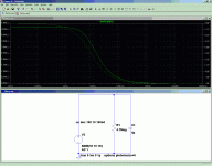
That's not too bad. And yeah, it's bootstrapped, so you can put it wherever you want, plate or cathode.
Some downsides: the 100k bias resistor must supply a minimum base current, which means saturation will necessarily be rather high. In this example, I found around 5V (more on this later). That's fine for a plate load. For a cathode load, it doesn't matter, because you wouldn't use this circuit: you'd use a circuit with more range.
Negative resistance is an obvious problem around reactances. Since it can be adjusted, this isn't necessarily a big problem, but it's something to be aware of.
Your analysis of ~4.5Mohm ignores some fundamental features of this circuit. For instance, it can do quite a bit better than this! The proof is in your negative resistance oscillator: if impedance can go negative, it must go to infinity somewhere inbetween. Unfortunately, such a point is likely only a balance point, with arbitrarily large resistance (positive/negative) on either side. The trick is to adjust that point so the curvature is as gradual as possible.
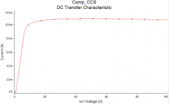
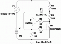
I have produced some DC sweeps which may be of interest. First: plain DC sweep, from 0-100V. This is using an identical circuit as shown above, using both 2N3904s for convienience (the model does not specify breakdown voltage, so the sweep can go beyond 60V quite easily). I cannot guarantee that my 2N3904 models are identical to yours.
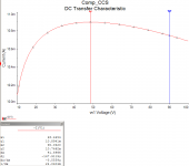
The second graph shows a zoom on the saturation region, with two points highlighted. The red cursor is approximately the infinite impedance point, showing a peak of 10.8941mA. The current drops off on both sides away from this point. The blue cursor indicates a point towards the edge of the sweep, at 90V, indicating a change of -0.1479mA, or an average incremental resistance (ugh, what an abomination of terminology) of -281kohms. (The actual incremental resistance at the blue cursor will be smaller than this.) That's not very good, and a cascode will outperform it easily.
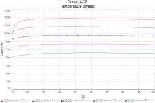
It gets worse. The third plot is a temperature sweep. At room temperature, everything is fine, but as temperature drops (the lowest is -50C, at the end of the military temperature range), saturation voltage rises considerably (to about 14V), and the saturation current is 21.9% higher. As temperature rises, saturation voltage falls, but current falls precipitously, by a whopping 36.9% at 150C!
The saturation voltage is affected by hFE, which "freezes out" at low temperatures, so it is reasonable to anticipate this effect. Likewise, Vbe drops at high temperatures, reducing the "threshold" voltage which appears on the current sense resistor.
A better current source might use a ratio of Vbe's at different currents to set the reference voltage (i.e., a bandgap reference), or an IC incorporating this method (e.g., TL431). Additionally, extra gain could be added to the system, to linearize it, flattening the curve.
Current sources can also be chained to a limited extent, eliminating the need to compensate the bias resistor, at the expense of a much larger "bias CCS bias resistor", which could be compensated in the same manner while having far less impact on total current.
Other options include below-ground sensing, so that the total circuit current is measured, thus including all base currents, and using a suitable reference and feedback loop to stabilize it.
Tim
Some downsides: the 100k bias resistor must supply a minimum base current, which means saturation will necessarily be rather high. In this example, I found around 5V (more on this later). That's fine for a plate load. For a cathode load, it doesn't matter, because you wouldn't use this circuit: you'd use a circuit with more range.
Negative resistance is an obvious problem around reactances. Since it can be adjusted, this isn't necessarily a big problem, but it's something to be aware of.
Your analysis of ~4.5Mohm ignores some fundamental features of this circuit. For instance, it can do quite a bit better than this! The proof is in your negative resistance oscillator: if impedance can go negative, it must go to infinity somewhere inbetween. Unfortunately, such a point is likely only a balance point, with arbitrarily large resistance (positive/negative) on either side. The trick is to adjust that point so the curvature is as gradual as possible.
I have produced some DC sweeps which may be of interest. First: plain DC sweep, from 0-100V. This is using an identical circuit as shown above, using both 2N3904s for convienience (the model does not specify breakdown voltage, so the sweep can go beyond 60V quite easily). I cannot guarantee that my 2N3904 models are identical to yours.
The second graph shows a zoom on the saturation region, with two points highlighted. The red cursor is approximately the infinite impedance point, showing a peak of 10.8941mA. The current drops off on both sides away from this point. The blue cursor indicates a point towards the edge of the sweep, at 90V, indicating a change of -0.1479mA, or an average incremental resistance (ugh, what an abomination of terminology) of -281kohms. (The actual incremental resistance at the blue cursor will be smaller than this.) That's not very good, and a cascode will outperform it easily.
It gets worse. The third plot is a temperature sweep. At room temperature, everything is fine, but as temperature drops (the lowest is -50C, at the end of the military temperature range), saturation voltage rises considerably (to about 14V), and the saturation current is 21.9% higher. As temperature rises, saturation voltage falls, but current falls precipitously, by a whopping 36.9% at 150C!
The saturation voltage is affected by hFE, which "freezes out" at low temperatures, so it is reasonable to anticipate this effect. Likewise, Vbe drops at high temperatures, reducing the "threshold" voltage which appears on the current sense resistor.
A better current source might use a ratio of Vbe's at different currents to set the reference voltage (i.e., a bandgap reference), or an IC incorporating this method (e.g., TL431). Additionally, extra gain could be added to the system, to linearize it, flattening the curve.
Current sources can also be chained to a limited extent, eliminating the need to compensate the bias resistor, at the expense of a much larger "bias CCS bias resistor", which could be compensated in the same manner while having far less impact on total current.
Other options include below-ground sensing, so that the total circuit current is measured, thus including all base currents, and using a suitable reference and feedback loop to stabilize it.
Tim
Attachments
More random goofage along the same vague idea...
I have no idea the frequency response or tempco.
MOSFET CGD (Miller cap) may run almost equal to
CGS (gate cap), due to the very low drain voltage.
On other hand, VGD is steady at one emitter drop.
Should not aggravate with non-linear capacitance.
Its one of those things that not in MOSFET model,
so you can't tell by the sim how the caps change
with bias.
Attachments
Last edited:
Thanks Richy! I had not seen those appear on Farnell.
Let the buyer beware with application of these to CCS circuit though. The devices are characterised purely for switching applications, with all the relevant saturation-region data provided. There's no Safe Operating Area curve, or any indication of where second-breakdown occurs [Second breakdown limits the current a transistor can pass to a lower limit than the power dissipation rating, when high voltage is applied].
For example, with a 1.5W transistor, running as a 10mA CCS, it may be possible to run 250V audio transients of 50ms duration in some transistors, but not in others.
Also note, that the 500V voltage durability only applies if the base-emitter is clamped [or low value resistor is connected]. In many CCS circuits, the 400V maximum would apply.
For 1 to 5mA circuits, and 350V B+ they should be safe though
Thanks Richy! I had not seen those appear on Farnell.
Let the buyer beware with application of these to CCS circuit though. The devices are characterised purely for switching applications, with all the relevant saturation-region data provided. There's no Safe Operating Area curve, or any indication of where second-breakdown occurs [Second breakdown limits the current a transistor can pass to a lower limit than the power dissipation rating, when high voltage is applied].
For 1 to 5mA circuits, and 350V B+ they should be safe though
I agree. Im using the new devices at 500V with a clamped base is as per MJ's cascade pnp fig 2.51 page 138 Valve amps 3rd edit, behaves excellent.
Going back to the MJE350's they exhibit somewhat suspect behaviour close at the Vceo 300V park, slight avalanching occurs on signal peaks, particulary at high frequencies. A sure warning sign to back off !
The obvious is to run SS devices well within their ratings. I'm using the new PBH types for UL 6mA forced CCS screen feeds. The results are amazing.
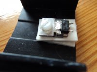
The SOT223 types need heatsinking to avoid runaway. At 20°C/W chip die to collector thermal resistance, I used a blown TO220 package with a double aluma-ceramic insulator for the lowest insulator thermal resistance and minimal "C". see pic.
richy
Attachments
- Status
- This old topic is closed. If you want to reopen this topic, contact a moderator using the "Report Post" button.
- Home
- Amplifiers
- Tubes / Valves
- New PNP HV tranny for anode CCS