I have two 6GM8 that I would like to put into use. Finding another similar one may prove to be difficult, so I would need to order quite a few to get matching tubes. I can order 12DL8 for cheap, and would like to do so.
Attached is a circuit I threw together with 1/2 6GM8 driving a 12DL8 (space charge tetrode). I am guessing you just attach the space charge grid to B+ through a resistor, correct? Does my topology look ok? Values good enough? Anything to change?
Suggestions and comments are welcome. Thanks!
Attached is a circuit I threw together with 1/2 6GM8 driving a 12DL8 (space charge tetrode). I am guessing you just attach the space charge grid to B+ through a resistor, correct? Does my topology look ok? Values good enough? Anything to change?
Suggestions and comments are welcome. Thanks!
Attachments
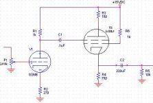
I think you have your control grid and screen grid reversed.
If you want it to act like a tetrode, you need to put a constant DC voltage (with respect to the cathode) on that screen grid. This can be done by running a resistor or a divider from B+ to the screen, then bypassing with a cap from screen to cathode. You'll also need some sort of grid leak from the control grid to ground. Not having my tube manual to hand, I can't comment on the choice of values or B+.
If you're using the tetrode as a CF, what's the function of that plate resistor?
Hi,
That's what I thought at first as well.
With the 12DL8 G2 is the control grid though.
The datasheet from Sylvania has some typical operation points for this tube:
12DL8
Cheers,")
I think you have your control grid and screen grid reversed.
That's what I thought at first as well.
With the 12DL8 G2 is the control grid though.
The datasheet from Sylvania has some typical operation points for this tube:
12DL8
Cheers,
Tom Bavis- Well that is cheaper than the price I was going to pay before.
I did notice the odd position of the screen grid, which is why I drew it like that. So, I can get rid of the plate resistor on the 12DL8? Any value that you think would work well on the screen grid? So, I do B+ to screen grid via resistor, then screen grid to cathode with cap? Ok... do-able. Any suggested values?
Thanks
Well, what you need to do is look at the expected screen current and scale the resistor accordingly to give you the desired screen voltage. The bypass cap ought to be chosen to give a rolloff a decade or so lower than the pole from the coupling cap. If you want to be REAL fancy, you can set up a floating regulator between cathode and screen, but that's fanaticism above and beyond the call of duty.
Hi,
In this case, quite probable.
But:
Let's not forget that since, in a penthode, the plate operates as little more than an electron collector, there is little reason to regulate it.
OTOH, regulating the screen is akin to regulating the anode in a triode.
A neat trick, since the penthode screen draws much less signal current than does the triode plate. By regulating the "surrogate plate" of the penthode (i.e., the screen) you prevent the screen grid from swinging with signal level and thereby you eliminate the conflict with the control grid for control over plate current.
Cheers,
If you want to be REAL fancy, you can set up a floating regulator between cathode and screen, but that's fanaticism above and beyond the call of duty.
In this case, quite probable.
But:
Let's not forget that since, in a penthode, the plate operates as little more than an electron collector, there is little reason to regulate it.
OTOH, regulating the screen is akin to regulating the anode in a triode.
A neat trick, since the penthode screen draws much less signal current than does the triode plate. By regulating the "surrogate plate" of the penthode (i.e., the screen) you prevent the screen grid from swinging with signal level and thereby you eliminate the conflict with the control grid for control over plate current.
Cheers,
If you look at the 1958 Beitman's under Motorola, you'll find a number of radios that use this type of tube - 12K5 and 12DL8 - as 1st adudio, driving a power transistor. Generally a 10M grid leak is used, which you'd connect grid- to- cathode in a cathode follower. Probably could go a bit lower... Generally no screen resistor or cathode resistor was used.
Beitman's on line: http://www.eskimo.com/~p0lez1/beitman/beitmanhome.htm
Beitman's on line: http://www.eskimo.com/~p0lez1/beitman/beitmanhome.htm
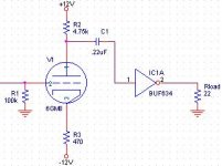
I now have one half of a 6GM8 set up for voltage gain no my bench... I don't have a noval socket laying around, so I just wrapped resistor legs and wires around the tube... Well, in short, it works, just not all that well. After a little warming, it sounds fine, but who can hear it?! It is way too quiet. Somewhere, I don't have enough gain. The mu (14) should provide mroe than enough voltage gain, and it is hooked to a BUF634 for current gain. Catode res is 470, plate res 4.7k, input res 100k. What have I done wrong? This little thing gets pretty darn warm too, considering I only have 24V going to it. Oh, in case it is important- the tube is running on +/-12V rails like the BUF. Any suggestions?
Hi,
Yes, but not under the working conditions you describe here.
Which one exactly? The 6GM8 or the 12DL8?
Sorry, but I'm more than a little puzzled on how you hooked the whole lot up....
Can you redraw the circuit diagram?
Cheers,
The mu (14) should provide mroe than enough voltage gain,
Yes, but not under the working conditions you describe here.
Oh, in case it is important- the tube is running on +/-12V rails like the BUF.
Which one exactly? The 6GM8 or the 12DL8?
Sorry, but I'm more than a little puzzled on how you hooked the whole lot up....
Can you redraw the circuit diagram?
Cheers,
Hi all-
Attached is the circuit I used for testing. I think all the values are the same, but I substituted some at times. The heater was undervoltage, which might have been a problem, but I don't see why one volt would make all the difference in the world.
Tube and buffer run off of +/-12VDC. Heater voltage was 5V. The overall response was very weak and somewhat fuzzy. Any ideas as to why?
Thanks
Attachments
Hi,
Other than the heater voltage, may I suggest to try the following:
Instead of running the tube from a bipolar supply, ground the cathode resistor and decouple it with at least 100µF/25VDC cap.
You should notice an increase in gain already...if more gain is required try lowering the value of that cathode R and see if it helps.
The ECC86/6GM8 is an odd tube that should be used with the curves in mind so that you stay away from the knee.
ECC86
Cheers,
Any ideas as to why?
Other than the heater voltage, may I suggest to try the following:
Instead of running the tube from a bipolar supply, ground the cathode resistor and decouple it with at least 100µF/25VDC cap.
You should notice an increase in gain already...if more gain is required try lowering the value of that cathode R and see if it helps.
The ECC86/6GM8 is an odd tube that should be used with the curves in mind so that you stay away from the knee.
ECC86
Cheers,
Needtubes-
I suspect you know, but others here may not:
The 12DL8 space charge tetrode and its ilk are NOT normal tubes.
Any tube will run with 12V on its plate, at very-very low current.
What these space-charge tetrodes do is run the full 12V into a grid (G1) near the cathode. That SUCKS the electrons off.
Most of them go to the G1. But a few miss G1 and end up loitering in the space just outside G1.
This thin fog of loose electrons is equivalent to a cathode. Virtual Cathode is the name of the effect, and you can get it in most tetrodes and pentodes between G2 and P.
In the 12V space-charge tubes, this virtual cathode is sucked on by the Plate, but flow is resisted by control voltage on G2 (signal grid).
So you have a triode with a very funny cathode that takes both a heater and a large DC bias current.
G1 has no resistor, just wired to the battery. Likewise the cathode really needs to be grounded.
Running a 12DL8 with G1 resistor and cathode resistor, you miss the benefits of space-charge design. What you have is a pretty crappy triode, easily beaten even at low voltage by many "normal" triodes.
For "plate power efficiency", these tubes are not very good. Most of the B+ current is the yank-out current from G1, which does not contribute to signal output. However the total power in heater and G1 is less than the heater power in an oversized tube that could handle the signal current with normal cathode action. Even so, we put 6 Watts in to get 0.040 Watts out. The only way this makes sense is in a car, where 12V is free and HV is expensive. In 1957, they could do the whole RF/IF strip of a car radio with small pentodes working 12V, and the audio power with a huge Delco power germanium eating 12V. But they could not get the 10mW-100mW needed to drive the audio output from any normal tube working on 12V, and a second transistor cost more than these whacky space-charge tubes.
These tubes are freaks and are specfically designed to be used a certain way.
Set it up just like the book. Cathode grounded or a very small resistor (10Ω ). G1 to +12V directly or through 10Ω. G2 takes signal and is biased with a 2Meg resistor to ground. Plate current is claimed to be 40mA at 12.6V, plate resistance is then 480Ω. If you want to resistor-load it, just 100Ω will tend to cause a 100*0.040= 4 volt drop, plate voltage falls to 12-4= 8 volts, a big change. We won't get 40mA with any decent resistor load (this tube is really meant for transformer coupling!). The Gm then will be somewhat less than 15,000µMho, be conservative and say 12,000µMho. 1/Gm is 80Ω, plate load is 100||480Ω=83Ω, voltage gain is about unity. Current gain may be huge for very-small signals, though because we have to bias the control grid to the edge of grid current to get any useful plate current, for large signals the current gain may be more like 10.
Hi,
I second that...absolutely baffling.
Need to tell the friends to stop calling me a walking library, I'm completely stunned.
Cheers,
Thank you, PRR, for taking the time to type a most interesting post.
I second that...absolutely baffling.
Need to tell the friends to stop calling me a walking library, I'm completely stunned.
Cheers,
- Status
- This old topic is closed. If you want to reopen this topic, contact a moderator using the "Report Post" button.
- Home
- Amplifiers
- Tubes / Valves
- low voltage tubes (6GM8 and 12DL8)