Or to look at it from the other side it is easier to remove transformer windings than put them back in.
My original point is the same as yours, that 0.68R value will require some adjustment on the bench.
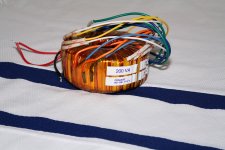
I removed four turns on each secondary, but left the wires at their original length as shown in the pictures. Then I went to the lab and measured. I got 5.25 V under load. I figured the voltage would drop some more once the high-voltage winding is loaded as well and I was within the granularity of one turn anyway. At this point I cut the wires and soldered the "exit wires" on. Had I been off by more, I would have put a turn back on or taken another turn off.
For the 0.68 ohm, I calculated 0.68 ohm. I then went to the lab and tried 0.68 ohm. And I measured 5.0 V with 0.68 ohm in series with the filament of the 5AR4. At this point I saw no point in any further experimentation as I had arrived at the target voltage. This was measured with the high-voltage secondary loaded, by the way.
~Tom
With my "new" transformer, I could supply the 5AR4 rectifier and the high voltage supply. But I needed a 12 V winding for the switchmode supply for the filaments of the 6J5 and 300B tubes I am using in my amplifier. Somehow, the thought of adding a winding to the 2T350 transformer didn't dawn on me until I saw George's post (thanks George!!).
For the 12 V winding, I decided to use the "pretty method" (i.e. magnet wire and kapton tape).
From post #1:
21 turns = 6.3 V --> 0.3 V per turn
Hence, for the 12 V winding, I'll need 12/0.3 = 40 turns.
To find the length of wire needed I wound ten turns of twine around the core and measured the length of the twine. I measured 5.5 feet for 10 turns, hence, 40 turns should take up 22 feet. I cut the wire 24 feet long to allow myself some slack.
I need to draw about 1.1 A on the 12 V winding - possibly slightly more if the mains voltage drifts low, so I settled on 1.5 A to leave plenty of margin. I went with a max current density of 3 A/mm^2, which yields a minimum wire diameter of 0.8 mm (AWG 20 = 0.812 mm diameter). The wire on the Antek 0512 (50 VA, 12 V) trafos I happen to have look to be more like 1.0 mm diameter, so after some waffling on the issue, I ended up getting a spool of 18 AWG (1.024 mm dia). At 1.5 A, this results in a current density of 1.8 A/mm^2 so I expect the winding to run pretty cool.
I need two 12 V windings, so I wound them "in parallel" and was able to wind both windings at the same time.
In summary:
40 turns AWG 18 (24 feet in length).
Measured output voltage (Vin = 120 V): 12.3 V @ 1.1 A load; 12.6 V @ 0 A load.
And lo and behold... it still fits in the CA-200 Antek steel cover.
~Tom
Attachments
Last edited:
I decided to use the "pretty method"
And it looks a whole lot better than mine.
If you had to take off four turns, wouldn't adding -4 turns be the same?
I'm asking, not telling. Adding reversed windings could be a stoopid idea.
Rarely see conventional bobbins so full that four extra turns could not
be threaded through the remaining window. There will be exceptions...
I'm asking, not telling. Adding reversed windings could be a stoopid idea.
Rarely see conventional bobbins so full that four extra turns could not
be threaded through the remaining window. There will be exceptions...
Last edited:
If you had to take off four turns, wouldn't adding -4 turns be the same?
Sure. Adding four turns in the opposite direction in series with the existing winding should have the same effect as removing four turns. However, adding turns is more expensive than removing turns. I'm not a fan of the "two steps forward, one step back" approach but that's my preference.
One could argue that the leakage inductance would be larger with four turns added "in reverse" as the distribution of the turns around the core would be rather uneven. But if you look at my pictures in the first post, it's pretty clear that the turns distribution that results from removing four turns isn't exactly even where the wires are terminated.
I went with the "pretty method" due to concerns with leakage inductance. Basically, the leakage inductance is formed by magnetic field escaping the core through the gaps between turns (that explanation should suffice for visual learners, others grab your EM books). This leakage field will induce currents elsewhere (think output transformers, input connections, etc) and result in hum. By keeping the wires evenly spaced I minimized the leakage. That's the theory anyway. Whether it makes a practical difference is a different story (experiment for another day). In any case, one should turn the toroid for minimum hum before bolting it to the chassis (see Douglas Self's article series in EE Times for this).
Another reason for choosing the "pretty method" is that I needed the transformer to fit the CA-200 steel "bell" from Antek...
~Tom
As long as we speak only of the outermost winding, thats fine.
Accessibility to unwind inner turns could prove to be interesting.
Very true. Having to unwind several layers of windings to access the one you want to modify would indeed suck.
~Tom
Not if one has some time to spare and curious about the workmanship of toroidal PT he has. ( sample )Very true. Having to unwind several layers of windings to access the one you want to modify would indeed suck.
good job Tom, i agree with what you have done as i would have done the same myself....i also make my own traffos and i aim for 5.25 ~5.4 volts open circuit voltage for the 5volt filaments and about 6.6~6.9 for the 6.3 volt filaments....reason is that under load, these voltages sag....i like the simple approach that works...congratulations....
If you had to take off four turns, wouldn't adding -4 turns be the same?
I'm asking, not telling. Adding reversed windings could be a stoopid idea.
Rarely see conventional bobbins so full that four extra turns could not
be threaded through the remaining window. There will be exceptions...
this is also workable, although there is an added series dc resistance penalty, than if 4 turns are unwound.....
- Home
- Amplifiers
- Tubes / Valves
- Turning a 6.3 V secondary into a 5 V secondary on an Antek 2T350