")
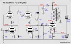
Probably you found this schematic from Tubecad.com. I haven't try this Akido driver but I would say there are so many different things contribute to the final sound result, such as OPT, bypass caps, signal coupling cap, tube type, B+ voltage, etc etc.... Everything counts.
Johnny
Johnny
The schematics look good, but Johnny is right about all the passive components having their influence on the sound.
Anyway what is not looking that well is the very high primary dcr of the output transformer. Maybe the transformer is a small one so that many primary windings are necessary to reach enough inductance and also to prevent the core from saturation. Likely the secondary dc resistance will be high too (not good for damping factor).
It is my experience that especially in these types of amplifiers lower dc resistances have a major (beneficial) influence on sound quality. But many people seem obsessed by having a 300B amplifier; in this design I guess that the output transformer is the limiting factor.
Pieter
The schematic looks fine, though the circuit will suffer from blocking distortion (aka "farting out") when driven hard. A good transient like the beat of a snare drum will do this and it sounds awful. I'm not saying that the amp will sound awful under all conditions, but if you crank the volume and hit the blocking distortion it will. There's a good description of how blocking distortion occurs here.
For a better 300B amplifier, I suggest looking at the Tubelab SE. You can buy a kit from George for a resonable price and there's plenty of help in the tubelab forum should you get stuck.
You can also wait a week or so. I'll be posting a build thread on a 300B amplifier that I've decided to name The Engineer's 300B Amplifier. As the name implies, it's a little over-engineered. But I really like how it sounds.
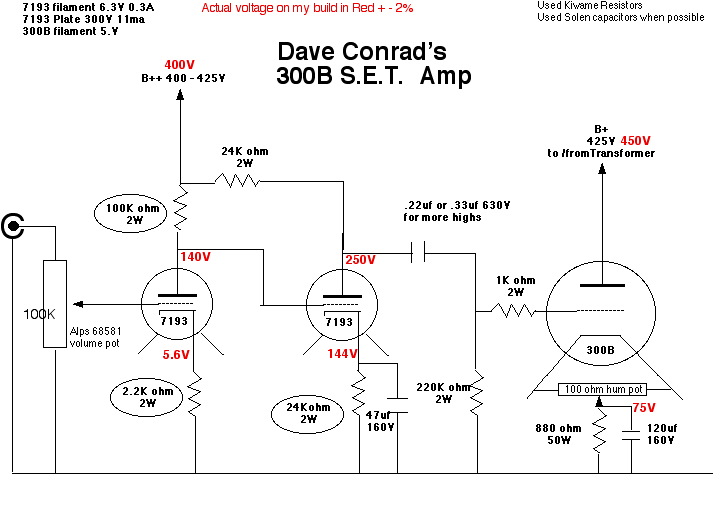
In the schematic you posted, the 300B runs at 417 V, 75 mA. That's mighty hot... I wouldn't go past 400 V, 65~70 mA. I've heard stories of 300B's doing thermal run-away, though, with the cathode resistor in place, that really should not happen.
~Tom
For a better 300B amplifier, I suggest looking at the Tubelab SE. You can buy a kit from George for a resonable price and there's plenty of help in the tubelab forum should you get stuck.
You can also wait a week or so. I'll be posting a build thread on a 300B amplifier that I've decided to name The Engineer's 300B Amplifier. As the name implies, it's a little over-engineered. But I really like how it sounds.
In the schematic you posted, the 300B runs at 417 V, 75 mA. That's mighty hot... I wouldn't go past 400 V, 65~70 mA. I've heard stories of 300B's doing thermal run-away, though, with the cathode resistor in place, that really should not happen.
~Tom
Don't quite agree Tom.
The Aikido driver stage has a pretty low output impedance; OK not as low as a Fet source follower a la Tubelab, but I don't think it will be so desastrous as you predict.
417V 75mA is 31 watts of plate dissipation. I have no problems using good quality 300B's like JJ with this kind of power, but there are many different 300B's around so that will depend on the particular 300B.
Pieter
The schematic looks fine, though the circuit will suffer from blocking distortion (aka "farting out") when driven hard. A good transient like the beat of a snare drum will do this and it sounds awful. I'm not saying that the amp will sound awful under all conditions, but if you crank the volume and hit the blocking distortion it will.
Maintaining this circuit while getting rid of blocking distortion one could move the .22 uF decoupling cap at the input, use +/-150V supply for the Aikido and eliminate the 100K + 10K grid resistors for the 300B as well. The connection of the 300B would be at 0V and one doesn't need to modify its cathode bias. Of course the amp could only be very slightly class A2 although far better than this with RC coupling, IMHO.
I don't like that huge DCR of the OPT (this is even higher than that of a 14K Hashimoto Sansui SE OPT!!) and prefer the cathode (source) follower solution however.....
45
P.S.
The 10K 300B grid resistor should limit the blocking distortion but I don't think it works with this tube. This is a more a remedy for small devices like a medium-low power pentode.
Last edited:
Maintaining this circuit while getting rid of blocking distortion one could move the .22 uF decoupling cap at the input, use +/-150V supply for the Aikido and eliminate the 100K + 10K grid resistors for the 300B as well. The connection of the 300B would be at 0V and one doesn't need to modify its cathode bias. Of course the amp could only be very slightly class A2 although far better than this with RC coupling, IMHO.
45
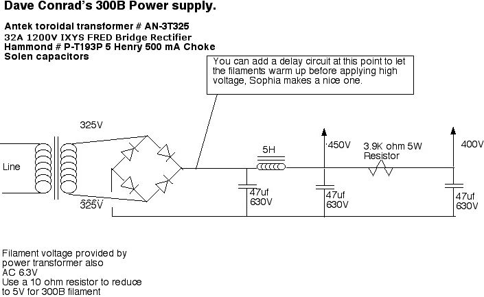
In order to have a smooth latch-up one can use solid state rectifiers for the +/-150V and tube rectifiers for the 300B. Best tube rectifiers are those like 12AX4GTB that already have a slow filament warm-up. In addition one could supply the rectifier filament with higher voltage and putting a (wirewound) resistor in series with the filament itself.
For example, one could use 2x12AX4GTB for a fullwave rectifier + 8R2 10W resistor between the two filaments (all in series) and a secondary voltage of 30V/0.6A instead of 25.2V/0.6. In conclusion one trades off 3VA for a nice 20 seconds natural delay for the 300B anode voltage.
45
I will be doing a 300b roughly based upon the JE Labs schematic. I may change around the front end a little. Although I am very tempted to use an aikido front end for it.
I currently use an aikido preamp. I just completed a moskido with an octal aikido front end to a MOSFET power stage. Next up is a 300b.
I think an octal version would be ideal...probably a single 6SN7 is what I will do. Broskie has published the CCDA. This topology is a single 6sn7 front end per channel wired a little differently than the JE Labs example.
I will agree, however, that the selection of OPT's, caps, and even resistors will all add up to the end result.
JE Labs 300b
Last edited:
Full article re the first post.
Aikido octal mono PCBs and 5687 PCBs and Aikido and 300B amplifiers
Rob
Aikido octal mono PCBs and 5687 PCBs and Aikido and 300B amplifiers
Rob
cjkpkg,
When you have an Aikidio preamp already, with presumably quite some gain, why not pick a driver tube with more juice than a 6SN7 (with its 10mA or so current).
You need some 50 VRMS to drive a 300B to the limit, see what amplification you have in your preamp and calculate what you'd need for the driver. There are many options here, and I think that a strong driver with some 30mA of current will be OK.
However, optimizing the schematic of the TS does not make much sense without looking for a higher quality output transformer.
Pieter
The Aikido driver stage has a pretty low output impedance; OK not as low as a Fet source follower a la Tubelab, but I don't think it will be so desastrous as you predict.
The output impedance is still 100's of ohm to upward of a few kOhm. Very high compared to the source follower's few ohms.
The reason I'm warning against the blocking distortion is that I've seen it in the lab and heard the results. I've watched the speaker cone lock at the excursion limit and recover a 10th of a second later (sometimes it took longer!). I've watched the o'scope trace flat-line while this was going on. I really don't like treating my speakers that way and I really don't like the sound it produces.
I see two possible solutions to this:
1) Make sure the 300B is never driven into A2 either by limiting the drive or by always running at low volume.
2) Insert circuitry that allows for a graceful transition into A2 and back to A1.
3) DC couple into the 300B. I like the idea of running a +/-150 V supply...
I realize that some people don't like "sand in their glass". That's fine. They're the ones listening to their systems...
I have tried the SRPP like the Aikido (2x 6J5), common cathode stages (6J5 followed by 6BX7), cathode follower (6BX7 and/or 6J5), as well as high-mu triodes. I have not been able to beat the sound quality I get with a source follower and I've not been able to get rid of the blocking distortion with anything other than a source follower. That's why I ended up going that route. Others are free to go different routes. All I'm doing is pointing out the tradeoffs.
417V 75mA is 31 watts of plate dissipation. I have no problems using good quality 300B's like JJ with this kind of power, but there are many different 300B's around so that will depend on the particular 300B.
That is a very good data point to have. Thank you. I'm using JJ tubes and am running them a bit conservatively. I really don't want to ruin a $100 tube...
~Tom
Last edited:
Tom,
Every driver stage you tried was rc coupled to the 300B, with 100k or so grid resistor?
I agree on the good working of the source follower, but for those wanting to avoid the sand another option might be the use of a grid choke instead of the grid resistor. Works very well also when applying fixed bias.
Pieter
Every driver stage you tried was rc coupled to the 300B, with 100k or so grid resistor?
I don't remember how the cathode follower was coupled to the 300B. I don't think I was comfortable running the cathode follower DC coupled as the bias for the 300B then becomes dependent on the Vgk of the cathode follower. I was more comfortable allowing it to depend on the Vgs of a source follower (call me neurotic...) Besides I needed gain... I may have operated all stages with AC coupling, which explains why I couldn't get rid of the blocking distortion.
But a DC coupled stage capable of sourcing current would work.
I agree on the good working of the source follower, but for those wanting to avoid the sand another option might be the use of a grid choke instead of the grid resistor. Works very well also when applying fixed bias.
In order for the choke not to kill your signal, it needs to be a fairly high inductance choke. However, to reduce the blocking distortion you need to be able to source current quickly to avoid discharging the coupling cap. The inductor would restrict the quick flow of current, hence, not help on blocking distortion.
~Tom
Anyway what is not looking that well is the very high primary dcr of the output transformer. Maybe the transformer is a small one so that many primary windings are necessary to reach enough inductance and also to prevent the core from saturation. Likely the secondary dc resistance will be high too (not good for damping factor).
I have a pair of the UBT-2's mentioned here. The transformers are not small, but the primary DC resistance is real. This will eat about 12% of your output power (about a watt on a 300B amp) and influence the damping factor in a negative way. Nevertheless the OPT's have a decent reputation and sound pretty good. I put Electra Prints in my amp. They do sound better.
Of course I have a biased opinion about the Tubelab SE, but anytime you see a coupling capacitor connected directly to the grid of the output tube you WILL have blocking distortion under some circumstances. Having a meaty driver tube can actually make the problem worse. So do DHT output tubes.
If you are building a budget or "Simple" amp this may be an acceptable trade off. If you are building a 300B amp, drive the 300B with a mosfet, a cathode follower, or an interstage transformer. Of course this makes the circuit more complex, but it is worth it, especially if you play dynamic music, and tend to turn it up.
- Status
- This old topic is closed. If you want to reopen this topic, contact a moderator using the "Report Post" button.
- Home
- Amplifiers
- Tubes / Valves
- Need advice on 300B circuit