Good evening everyone,
I apologize for some of the bonehead threads I have asked about things like ‘Using just 12AU7s for a Phono Stage’ and ‘3-12AU7 Preamp’. I just don’t know that much about the working of tubes to know how crazy I sound.
I also tend to ask very vague questions which causes more issues than it fixes, so I am going to try to be careful and ask advice for a pre-amp with giving more of a background in hopes that it will cause less frustration to the members offering their assistance.
I am looking to build a pre-amp that is used for home listening that will match my system well now and possibly with other amp builds in the future.
Here is my system at this time
Krell - KAV 400xi – Integrated Amp – 250W – Using the Pre-out only
Apple TV – Digital Music Source – Files are Apple lossless compression
POS – Turntable and Phono stage – DIY turntable and Phono stage to be built at a later date
Martian Logan – Aeon – Electrostatic Speaker
DIY Sub – Martian Logan Drivers and Rythmik 600w non servo amp
6SL7GT (JAN-Sylvania)/ 6V6S (JJ) PP Amp – [6V6G Marconi to replace the 6V6s JJ just arrived today]
I have the following tubes at this time. If none of these will work, I will just save them for a later build.
3 – RFT – ECC82
4 – RCA – 12AU7 Clear Top
4 – Siemens – C3G and C3M
2 – Tung-Sol 6SL7GT
I also have a lot that was bought for $20 off EBay. I figure take a chance for the $20 and hope for the best. I think I have some that may work.
For the power supply, I had already purchased an Antek 200v Toroidal – 2 x 200v / 100va outputs and 2 x 6.3 / 3A outputs. I had also built the PSU for Bruce’s Forewatt Preamp. I can change the resistors as needed to raise or lower the voltage depending on the pre-amp design chosen.
Under louder listening conditions (Turn it up and work around the house), The volume of the Krell is around 60/70 out of 120 (just over midway). This holds true using just the Krell alone or along with the Tube amp.
I don’t believe that I need much gain at all, but I don’t want to just use an attenuator (no fun to build).
Does anyone have any good ideas of a circuit that is not overly complex that will yield good results? Please keep in mind that I am a Greenhorn, so some of the questions you ask may not sink in at first. I am not trying to ride coat tails from someone’s hard design work, I just love the build and do not have experience in circuit design.
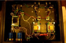
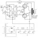
Also I am attaching a schematic of the amp so you will know how it is build. Heck, maybe there will even be room for improvement on that.
Thanks for you time and patience.
Cheers
Brian
I apologize for some of the bonehead threads I have asked about things like ‘Using just 12AU7s for a Phono Stage’ and ‘3-12AU7 Preamp’. I just don’t know that much about the working of tubes to know how crazy I sound.
I also tend to ask very vague questions which causes more issues than it fixes, so I am going to try to be careful and ask advice for a pre-amp with giving more of a background in hopes that it will cause less frustration to the members offering their assistance.
I am looking to build a pre-amp that is used for home listening that will match my system well now and possibly with other amp builds in the future.
Here is my system at this time
Krell - KAV 400xi – Integrated Amp – 250W – Using the Pre-out only
Apple TV – Digital Music Source – Files are Apple lossless compression
POS – Turntable and Phono stage – DIY turntable and Phono stage to be built at a later date
Martian Logan – Aeon – Electrostatic Speaker
DIY Sub – Martian Logan Drivers and Rythmik 600w non servo amp
6SL7GT (JAN-Sylvania)/ 6V6S (JJ) PP Amp – [6V6G Marconi to replace the 6V6s JJ just arrived today]
I have the following tubes at this time. If none of these will work, I will just save them for a later build.
3 – RFT – ECC82
4 – RCA – 12AU7 Clear Top
4 – Siemens – C3G and C3M
2 – Tung-Sol 6SL7GT
I also have a lot that was bought for $20 off EBay. I figure take a chance for the $20 and hope for the best. I think I have some that may work.
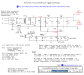
For the power supply, I had already purchased an Antek 200v Toroidal – 2 x 200v / 100va outputs and 2 x 6.3 / 3A outputs. I had also built the PSU for Bruce’s Forewatt Preamp. I can change the resistors as needed to raise or lower the voltage depending on the pre-amp design chosen.
Under louder listening conditions (Turn it up and work around the house), The volume of the Krell is around 60/70 out of 120 (just over midway). This holds true using just the Krell alone or along with the Tube amp.
I don’t believe that I need much gain at all, but I don’t want to just use an attenuator (no fun to build).
Does anyone have any good ideas of a circuit that is not overly complex that will yield good results? Please keep in mind that I am a Greenhorn, so some of the questions you ask may not sink in at first. I am not trying to ride coat tails from someone’s hard design work, I just love the build and do not have experience in circuit design.
Also I am attaching a schematic of the amp so you will know how it is build. Heck, maybe there will even be room for improvement on that.
Thanks for you time and patience.
Cheers
Brian
Attachments
Brian,
IMO, the easiest way to build a nice line stage that has a small amount of gain is by employing 12B4s. There are plenty of 12B4 designs in the archives, including mine.
As for the amp, it uses a paraphase (seesaw) splitter/driver. That topology has few (zero?) advocates around here. You have what seems like decent stuff in the B+ PSU. Rearrange that to yield 355 V. and you are on your way to having an "El Cheapo" variant. You don't have to scrap your chassis, as adapters made from Noval sockets and Octal plugs are easy enough to construct.
Please notice that a preamp is not needed with an "El Cheapo", if the signal source(s) are digital. BTW, the 'AQ5 shown in the schematic is, for all practical purposes, a 6V6 in a 7 pin mini package.
Attachments
Eli - Thanks, I will start looking at 12B4 circuits.
Out of curiosity, why does no one like the 'paraphase (seesaw) splitter/driver'?
Is it a poor of difficult design to work with, or does it just provide less than desirable results?
I just picked that amp from diyaudioprojects.com out the list of schematics. It looked fairly straight forward to build.
But, of course about 3/4 of the way through the build, I come across this site. So I guess we can call that a learning lesson.
Thanks again
Brian
The information is very helpful.
For a first preamp, I would personally choose Aikido Cathode Follower PCB . Advantage is a wide range of tube choices, a PC board and a good manual.
If I was building someone else's design, I would build this: The Heretical Preamp
SYclotron Audio The Heretical Preamp.
Both have no voltage gain.
However, the Forewatt will work well, and if you have the parts already, there is no reason not to build it. Just understand its limitations, which are load sensitivity related.
HTH
Doug
Good evening all,
I believe that I am going to go with the 12B4 option. Everyone seems to have great opinions about this tube's use for a low gain preamp.
I have often thought about building one of the kits mentioned, but I guess I love doing things the hard way. Maybe one will be built in the near future.")
I was intending on going with the Forewatt, but I believe that after further reading, that the 12B4 will a better choice for me. I can't really put my finger on why, just a gut feeling.
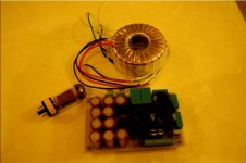
One thing that I have already completed is the power supply. Is there a circuit that I can build on a small board that will get the voltage down and constant current that is needed? I can also change some of the resistors in the circuit to knock the voltage down.
I just didn't want to scrap the PSU and start over. I am using a AnTek 200v 100va Toroid that has two 115v inputs and two 200v outputs.
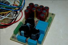
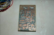
Attached is the schematic and a couple of photos. I did use a handful of Elna Cerafines on the heater side that I had on hand instead of the 2 caps that the diagram called for. Probably overkill, but it works.
Any ideas would be helpful
Thanks
Brian
I believe that I am going to go with the 12B4 option. Everyone seems to have great opinions about this tube's use for a low gain preamp.
I have often thought about building one of the kits mentioned, but I guess I love doing things the hard way. Maybe one will be built in the near future.
I was intending on going with the Forewatt, but I believe that after further reading, that the 12B4 will a better choice for me. I can't really put my finger on why, just a gut feeling.
One thing that I have already completed is the power supply. Is there a circuit that I can build on a small board that will get the voltage down and constant current that is needed? I can also change some of the resistors in the circuit to knock the voltage down.
I just didn't want to scrap the PSU and start over. I am using a AnTek 200v 100va Toroid that has two 115v inputs and two 200v outputs.
Attached is the schematic and a couple of photos. I did use a handful of Elna Cerafines on the heater side that I had on hand instead of the 2 caps that the diagram called for. Probably overkill, but it works.
Any ideas would be helpful
Thanks
Brian
Attachments
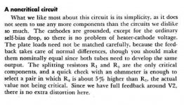
There is always the danger of fashion in audio. However, this phase splitter can provide poor balance. Essentially, the second triode is acting as an anode follower - like the inverting op-amp configuration. Two snags arise from that. A triode does not have the near infinite open-loop gain of an op-amp, so the gain of the circuit is not the -1 that simple theory predicts. The 47K resistor loads the error voltage at the junction of the two 220K resistors, so a lowish gain is reduced further. The effective open-loop gain might be only 10-15, so you could get imbalance of over 5% quite easily even with perfect resistors. The two triode anodes have quite different impedance, much lower for the second triode so there is a risk of HF imbalance as the two halves of the output stage will have similar input capacitance.Out of curiosity, why does no one like the 'paraphase (seesaw) splitter/driver'?
The first imbalance can be improved by adding a resistor to one of the 220K. The HF imbalance is harder to fix. At least your circuit uses 6SL7 so you have reasonable gain to start with - I have seen this done with 6SN7 or similar where the open-loop gain for the phase splitter might be only 5!
That power supply work you've done is very nice, great soldering work! But on the original topic, my go-to tube for moderate gain/high linearity is the 6SN7 or it's 9-pin equivalent, the 6CG7, an Aikido using these makes a very nice low noise, low-gain (about 10) linestage. I have several 6CG7 waiting to become a cathode follower preamplifier myself, although a 12B4 is also an excellent choice, I just simply don't have any.
DF - Thanks for the info, I dont totally understand everything you said, but I think I get the idea. I'm not fluent in Tube yet.
What value resistor would you propose adding? This would go in parallel with the 220K, correct?
This is one way to look at it, if it is 8% out of balance, then it is 92% in balance.
Since I have the amp out, I'll go ahead and make that adjustment.
Also, can anyone point me in the right direction to get the PSU to around 90-100v and 40ma. Most of the 12B4 circuits i have looked at show a CCS at 90ish volts and about 20ma per tube.
Thanks
Brian
Your easiest answer is a Voltage regulator.
there should be a high voltage example in the National Semiconductor app note for the 317 voltage regulator chip. Its explained on Page 342 of Morgan Jones "Building Valve Amplifiers, Third Edition".
The other option is to download PSUD2 and experiment with the resistors until you found a solution.
HTH
Doug
Doug - I've got PSUD2, so I will try that. Since the CCS in some of the threads look different than the PSU that I have, I didn't know if that was an okay approach or if there was something more to it.
Thanks a bunch, this puts me one step closer...
I'll grab a copy of the reading material that you suggested as well.
Thanks again for the help
Brian
Thanks a bunch, this puts me one step closer...
I'll grab a copy of the reading material that you suggested as well.
Thanks again for the help
Brian
Here's a similar phase splitter:
http://www.grommesprecision.com/grommes/assets/pdf/littlejewelreview.PDF
Here's another one:
The Valve Wizard
Different paraphase:
http://www.audionotekits.com/kit4schem.gif
http://www.grommesprecision.com/grommes/assets/pdf/littlejewelreview.PDF
Here's another one:
The Valve Wizard
Different paraphase:
http://www.audionotekits.com/kit4schem.gif
DF - I can do that. I have plenty of 47k handy.
One thing i was wondering is this.
Is there a measurement that can be taken with a DMM that will give an idea of what is out of balance for each channel? If so couldnt the resistor be placed on the on either 270k as needed to balance the circuit better?
My assumption to the above question would be no, because someone would have figured that out before me, but i figured id ask.
Thanks again to everyone
Brian
Or swap the lower 270K for a 330K - although this might take it too far.
I wouldn't worry about it.
Attachments
I wouldn't worry about it.
I would. It's the classic, "Yes, it's nonlinear, but feedback cleans that up." It's always better to have a good, linear, well-balanced circuit to begin with, THEN apply feedback to drop the source impedance and increase linearity further. When feedback is limited (which it is with the posted circuit), the imbalance and nonlinearity is not well suppressed.
It's no harder to start with an intrinsically good circuit.
It's no harder to start with an intrinsically good circuit.
Ok, I think we have established that I picked a poor circuit for this the amp and no one likes this type of circuit due to various issues that it has. At least I know what to stay away from for now on.
I am just trying to make a bit of sense of this. Will this change be marginal, dramatic or a crap shoot? I know you guys have been doing this for a long time so I just don't know which way to go since there are 3 different opinions.
For now do I,
Leave it alone
Add the 47K
Measure and adjust one side 5% higher than the other per the paragraph in the above response from Stalker?
Once I take care of that this, I assume it will be about as good as it will get and should by okay until I decide to build a better amp?
Thanks for all the help and advice
Brian
That sounds good to me.Once I take care of that this, I assume it will be about as good as it will get and should by okay until I decide to build a better amp
Doug
cbj591, better in audio is relative. One designer's meat is another designer's poison. Since you like DIY you can try different circuits and judge for yourself.
It is. He will need a negative supply not to mention the CCS needed for best balance. And after all that work there's no guarantee it will sound better. This is not a personal opinion.
Frankly, I couldn't care less what you build but, think about it, a simple circuit like the the paraphase or cathodyne splitter has been used countless times; if it was good enough for designers with lots of experience I see no reason why it shouldn't be good enough for you.
I will say no more, after all, this is pretty pointless. If you're not happy with the sound just try another circuit. As simple as that.
It's no harder to start with an intrinsically good circuit.
It is. He will need a negative supply not to mention the CCS needed for best balance. And after all that work there's no guarantee it will sound better. This is not a personal opinion.
Frankly, I couldn't care less what you build but, think about it, a simple circuit like the the paraphase or cathodyne splitter has been used countless times; if it was good enough for designers with lots of experience I see no reason why it shouldn't be good enough for you.
I will say no more, after all, this is pretty pointless. If you're not happy with the sound just try another circuit. As simple as that.
Last edited:
Frankly, I couldn't care less what you build but, think about it, a simple circuit like the the paraphase or cathodyne splitter has been used countless times; if it was good enough for designers with lots of experience I see no reason why it shouldn't be good enough for you.
I will say no more, after all, this is pretty pointless. If you're not happy with the sound just try another circuit. As simple as that.
Actually, compared to my Krell KAV-400xi, I think it is a pretty good sounding amp. I was hoping that the advice for the mods would help improve the sound more.
Thanks for the advice
Brian
- Status
- This old topic is closed. If you want to reopen this topic, contact a moderator using the "Report Post" button.
- Home
- Amplifiers
- Tubes / Valves
- Requesting advice on a pre-amp build. I'm working on asking realistic questions.