Hello all,
Just wanted to share my newest project...
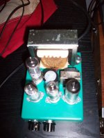
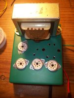
It's tubes are as follows:
35w4
12AT7
12AT7
50c5
It's built into a 6" x 4" x 1" enclosure, quite small...
Sounds amazing, very bluesy, even with a crap 1970s 8" that I dumpster dived for a few weeks ago...ever so slight of a hum, barely noticeable,
All tubes are pulled out of 2 1950s radios,
Total Cost: $35
Tell me what you think...
Just wanted to share my newest project...
It's tubes are as follows:
35w4
12AT7
12AT7
50c5
It's built into a 6" x 4" x 1" enclosure, quite small...
Sounds amazing, very bluesy, even with a crap 1970s 8" that I dumpster dived for a few weeks ago...ever so slight of a hum, barely noticeable,
All tubes are pulled out of 2 1950s radios,
Total Cost: $35
Tell me what you think...
Attachments
Well, just to update...
I left it on for 12 hours to make sure that nothing melted and everything is A OK. I'm about to start working on another design that uses the popular 50L6GT and the 12AX7 (Although I may substitute 2 12AT6 instead)
Took it to the pawnshop and they gave me $100, not bad for a $35 investment...")
I left it on for 12 hours to make sure that nothing melted and everything is A OK. I'm about to start working on another design that uses the popular 50L6GT and the 12AX7 (Although I may substitute 2 12AT6 instead)
Took it to the pawnshop and they gave me $100, not bad for a $35 investment...
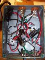
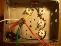
Yes, I know that I need to add a fuse, maybe 1 Amp? The chassis is grounded to the negative lead of the capacitor, and all the other grounds ground there too...
It doesn't have a bad hum at all, but next time I will run the output transformer perpendicular.
This is my first amp, so any feedback will be more than welcome. One thing that I didn't count on was the heat generated by these tubes. Now I understand why you can't just pack all of them onto a small chassis. Live and learn I guess.
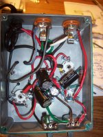
Also, should I ground the center tap from the AC in? I used the transfo. backwards to get the dual primaries to run the heaters and the other to run the B+ and B++.
Thanks
HUH? Im talking about grounding the chassis to the green wire of a 3 wire plug.
AKA its a safety thing were if your neutral happens to loose contact with the chassis, your finger doesnt complete the circuit to hot. Thats all ground is, a non current carrying backup to neutral. ALL metal chassis's should have it.
Ya a 1amp fuse is fine.
To de hum you can try the following:
Lift the potential of heaters 60-100v
Convert Heaters to DC
keep signal wires away from power wires
Make all the wires cross at 90 degrees.
I only have a 2 prong cord that isn't polarized...I thought that I would be ok if i used a isolation transformer...
Which is fine if it is an isolation transformer in a SEPARATED box.
You have raw AC going into a metal box. You do not have isolated AC going into a metal box.
If your transformer develops a short, or the cable frays your in trouble. Want to know worse case? The Hot touches the chassis. Nothing happens, the amp works great. However now the amps chassis has been lifted to 120 volts. So the next person that goes to shut it off, in bare feet, while walking on a concrete floor, gets dropped like a rock.
Isolation transformers are there so that the equipment you're working on doesnt have a potential to ground so you dont get shocked, but they cant be in the same metal chassis.
Which is fine if it is an isolation transformer in a SEPARATED box.
You have raw AC going into a metal box. You do not have isolated AC going into a metal box.
If your transformer develops a short, or the cable frays your in trouble. Want to know worse case? The Hot touches the chassis. Nothing happens, the amp works great. However now the amps chassis has been lifted to 120 volts. So the next person that goes to shut it off, in bare feet, while walking on a concrete floor, gets dropped like a rock.
Isolation transformers are there so that the equipment you're working on doesnt have a potential to ground so you dont get shocked, but they cant be in the same metal chassis.
I'm sorry, are you saying that a 3-prong cord is a MUST? If this is the case, perhaps it's worth the extra $5 investment.
Thank you
I'm sorry, are you saying that a 3-prong cord is a MUST? If this is the case, perhaps it's worth the extra $5 investment.
Thank you
I live in 230V land, but yes, even with 120V, if you have a metal chassis a three prong cord is a MUST. (Here it is a legal must too, if you want to sell it.)
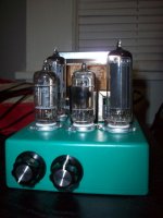
I really think those two smaller tubes look like 12AV6's or 12AT6's.Hello all,
Just wanted to share my newest project...
It's tubes are as follows:
35w4
12AT7
12AT7
50c5
It's built into a 6" x 4" x 1" enclosure, quite small...
Sounds amazing, very bluesy, even with a crap 1970s 8" that I dumpster dived for a few weeks ago...ever so slight of a hum, barely noticeable,
All tubes are pulled out of 2 1950s radios,
Total Cost: $35
Tell me what you think...
I don't do much with tubes, but I sure do remember what the ones from the old All-American 5 miniature tube radio design look like.
OK, I'm going to go by the thrift shops today to look for a cord...
I guess that everything else is OK, just need that cord. Next time I'm going to do a better job grounding too, use a bigger box, and fit a power switch inside...
Thanks for the input. I'm going to try a 50L6GT next, 2 channel, using solid state diodes and a diode dc step up. I'll post the schematic when I'm done with it...
Do not use 12BE or BA tubes. These are not preamp type tubes, they are heptode type converters used in the tuning sections of radios.
Check out the differences here:
http://www.mif.pg.gda.pl/homepages/frank/sheets/093/6/6AT6.pdf
http://www.mif.pg.gda.pl/homepages/frank/sheets/127/1/12BE6.pdf
Check out the differences here:
http://www.mif.pg.gda.pl/homepages/frank/sheets/093/6/6AT6.pdf
http://www.mif.pg.gda.pl/homepages/frank/sheets/127/1/12BE6.pdf
- Status
- This old topic is closed. If you want to reopen this topic, contact a moderator using the "Report Post" button.
- Home
- Amplifiers
- Tubes / Valves
- DIY 50C5 mini amp...