I did actually consider that amp but I got scared when I saw it needs a -160Vdc. That means I would need an extra high voltage trafo, and im trying to keep costs down.
Do a search for the 6GK5/6V6 music machine. It's the updated version, and only needs -66V for the CCS. I've built the 6GK5/EL34 version, and it's the nicest sounding amp in the collection so far.
The -66VDC is supplied by a tiny 44V toroid.
http://www.diyaudio.com/forums/tubes-valves/149211-6v6-music-machine-build-help.html
Last edited:
I did actually consider that amp but I got scared when I saw it needs a -160Vdc. That means I would need an extra high voltage trafo, and im trying to keep costs down.
In the overall costs of implimenting the music machine (as it should be done), an additional small trafo is negligible. It doesn't need to be a high power piece of iron since its only setting up a voltage for the first stage - some 15ma if I recall correctly.
Poinz does some very convoluted connections to make a couple of common PTX's work, but the required combinations can be acheived in a number of ways.
Where did you read it? I have serious doubts about that.
Gernsback Library Inc.
april 1956
Crowhurst and Cooper
"High Fidelity Circuit Design"
chapter 6
Drivers and Inverters
I'm not arguing against, I actually like the Mag style, and I believe it sounds very good, even with theoric weaknesses..
Last edited:
Making the input a 6SL7 LTP, to a 6SN7 CF Driver, to the 6V6 with 12v battery fixed bias and the screens to the UL taps. Wouldn't be that much more in terms of complexity... (And maybe some Shade...)
Athos
So, completely redesign it then? Sounds like a complex response to a simple problem - the 6V6 doesn't need huge voltage at G1 to drive it, just an appropriate driver/splitter. Why throw another pair of tubes at the issue? Ditch the SL7 and go SN7 voltage amp to SN7 concertina splitter. Job done.
So, completely redesign it then? Sounds like a complex response to a simple problem - the 6V6 doesn't need huge voltage at G1 to drive it, just an appropriate driver/splitter. Why throw another pair of tubes at the issue? Ditch the SL7 and go SN7 voltage amp to SN7 concertina splitter. Job done.
Sorry, half snark, should have left it alone
")
Athos
May I immodestly intrude?
Check "El Cheapo" out. The 12AT7 has a higher gm than either the 6SL7 or the 6SN7. High gm and low RP make for better performance in a driver.
For all practical purposes, the 'AQ5 shown in the schematic is a 6V6 in a 7 pin mini package. Zero parts value changes are needed to build with 6V6s.
Triode wired "finals" yield approx. 6 WPC. If the O/P tubes are set up in ultralinear mode, about 12 WPC are available.
Attachments
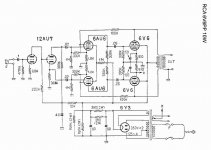
Tube rolling might improve it and I don't know way the first cap after rectifier is so high! I think it should be 30.
I've seen that a lot with these old designs. They were trying to build it on the cheap, and resistors are a good deal cheaper than ripple chokes, but half as effective for ripple attenuation. They abused the hollow state diodes with over sized reservoir capacitors. They were counting on an atechnological public to be unaware that having to constantly replace the 5Y3s wasn't normal. It didn't hardly matter when you could go to any grocery store, pharmacy, radio/TV repair shop and get replacements for a $1.50 (or whatever they cost).
Of course, a big reservoir capacitor like that is going to bust the specs for Isurge. That should be less than half that size. 34uF behind a 5U4GB comes to something like 815mA of Isurge, and that one is rated for a max of 1.0A of Isurge.
You need to get that capacitor down in size, and use an LRC ripple filter. If you want to keep it cheap, then consider an active decoupler after the reservoir capacitor.
Sorry about the order as I saw a spelling mistake and ended up deleting post because I was past edit time.
I actually can't find any evidence that that amp was ever produced. The RCA engineers in that RC19 manual explain they are "not necessarily examples of commercial practice." However the commercially produced SP-20 quad tube 20W/CH version has choke PS with the right cap values.
Thanks!
Randy
I actually can't find any evidence that that amp was ever produced. The RCA engineers in that RC19 manual explain they are "not necessarily examples of commercial practice." However the commercially produced SP-20 quad tube 20W/CH version has choke PS with the right cap values.
Thanks!
Randy
Last edited:
Gernsback Library Inc.
april 1956
Crowhurst and Cooper
"High Fidelity Circuit Design"
chapter 6
Drivers and Inverters
Thanks.
Chapter 6. Pg 127-135. Seesaw or anode follower.
Read it again. He likes the circuit.
Thanks for the suggestion Eli.
What are the voltages (or range of voltages) for B+, B2+ and B-?
The needs of the 12AT7 splitter/driver rule the roost. The 'T7 sounds very good with 200 to 220 V. on the plate and an IB of 3 mA. Bringing the B+ in at 355 V. is just about perfect. The N-77U isolation trafo will not get there, by itself. A Triad VPS24-1800 has 2X 1.8 A./12 V. windings which will provide heater power to the O/P tubes and the 12AL5 and also provide some boost for the B+ rail. Wire pairs of 6V6 heaters in series.
From the very beginning, "El Cheapo" was and still is a cost conscious project. Quite a few Volts get dropped in the B- circuitry shown and 40 V. of B- should be enough. However, the $13.41 Allied 6K27VF trafo makes tightwads smile.
A full set of power magnetics can be ordered from Allied. In addition to the stuff already mentioned, at $7.74, a Triad C-24X neatly fills the B+ choke requirement.
The circuitry benefits from good O/P "iron" and DynaClone Z565s kick butt. If your bank balance can't stand that expense, Edcor has some decent stuff. Unfortunately, the guitar amp trafo shown no longer represents good value.
The lengthy saga of "El Cheapo" can be found here.
wow! thats a mighty long thread!
where do I find the final version of the circuit?
where do I find the final version of the circuit?
The graphic I previously uploaded is "current". Revisions have not been made, but probably should. Look here for how to set up the B+ boost.
Thanks.
Chapter 6. Pg 127-135. Seesaw or anode follower.
Read it again. He likes the circuit.
Nice reading, the first time I have seen it discussed with pros and cons of different variations.
The needs of the 12AT7 splitter/driver rule the roost. The 'T7 sounds very good with 200 to 220 V. on the plate and an IB of 3 mA. Bringing the B+ in at 355 V. is just about perfect. The N-77U isolation trafo will not get there, by itself. A Triad VPS24-1800 has 2X 1.8 A./12 V. windings which will provide heater power to the O/P tubes and the 12AL5 and also provide some boost for the B+ rail. Wire pairs of 6V6 heaters in series.
From the very beginning, "El Cheapo" was and still is a cost conscious project. Quite a few Volts get dropped in the B- circuitry shown and 40 V. of B- should be enough. However, the $13.41 Allied 6K27VF trafo makes tightwads smile.
A full set of power magnetics can be ordered from Allied. In addition to the stuff already mentioned, at $7.74, a Triad C-24X neatly fills the B+ choke requirement.
The circuitry benefits from good O/P "iron" and DynaClone Z565s kick butt. If your bank balance can't stand that expense, Edcor has some decent stuff. Unfortunately, the guitar amp trafo shown no longer represents good value.
The lengthy saga of "El Cheapo" can be found here.
I would have some more questions about it.. Decided to post them here so that others can see, even if I asked some of them in private mail.
First about using a ECC82 LTP.. Could the lower gm be compensated by using larger resistors at anodes, and by using cathode follower drivers? Or does the ECC82 suck so hard that they aren't worth using even if you have them at hand?
And how about ECC85, E88CC or E188CC?
Secondly, I take it that you could use generic isolation transformer (230V primary, 2x 115V secondary) for B+s and generic 6V transformer for heaters? And how about using Edcor's transformers as OPTs, I was mainly thinking about their XPP series?
Also, is the driver circuit beefy enough for paralleling two output tube pairs?
First about using a ECC82 LTP.. Could the lower gm be compensated by using larger resistors at anodes, and by using cathode follower drivers? Or does the ECC82 suck so hard that they aren't worth using even if you have them at hand?
Larger plate loads can compensate up to a point. However, the ECC82 (12AU7) has a u= 20, and the 12AT7 has a u= 60. VTs aren't like transistors, and you can't drive the gain up at will. Even with an infinite plate load, an ECC82 won't give more voltage gain than 20. With passive loads, you'll be hard-pressed to get a gain higher than ~16.
As for how they sound, audiophool folk wisdom isn't necessarily credible. However, looking up schemos for circuits using the ECC82 turned up lots of RF, digital, and quasi-digital applications, but relatively few audio applications. Take that for what it's worth.
You might be able to find some decent loadlines, or specialized applications like LTP phase splitters where it works just fine, even if it's inferior as a general purpose, audio, small signal amp. Otherwise, consider the similar 6FQ7, which works just great in audio.
And how about using Edcor's transformers as OPTs, I was mainly thinking about their XPP series?
Edcor's have a pretty good reputation.
- Status
- This old topic is closed. If you want to reopen this topic, contact a moderator using the "Report Post" button.
- Home
- Amplifiers
- Tubes / Valves
- Have anyone built this 6V6 amp?