Sorry Wavebourn to quote you again but I cannot resist to comment this!
If the amp works in class A a fixed bias is not needed only for a textbook example. You yourself have already mentioned a series of issues that actually make fixed bias more desirable in most situations....
If then we talk about the sound is even more desirable.
Cathode bias is just simpler and more suitable for a novice.")
I can't say for a novice since I still have my EE diploma and have four decades of experience, so I can say for myself only: everything has positive and negative sides. The art and science of engineering is optimization. You can concern about some effects more than of others, so your set of criteria and their weights will be different, while I may weight the same criteria differently. And my own conclusion is that autobias for class A tube amps is right and logical solution, while for class AB it does not work so fixed bias must be used. Another way to go is an adaptive bias that works as a S/H that opens DC feedback through an integrator when comparator senses low signal level and closes when signal level goes up. It has advantages of both fixed and autobiases.
But it is too complex for novices, unless is available in ready to use kits. I plan to manufacture such kits soon.
Off topic now, but you mean something comparable to John Broskie's sliding bias schemes?
Sorry; I don't follow John's blog.
I mean, feedback by current with time constant of an integrator controlled by signal level. I am not sure if somebody did that before. In my Alligator project I used similar approach, but it had a gate only, with constant time constant of an integrator. The main mistake people do when design such solution is too hot starting point, so idle current tends to drift to higher value on long loud passages (contrary to simple cathode bias scheme). I don't know how John solved this problem.
When such kits are not available, or too costly for the project, a simple 510 Ohm Caddock resistor shunted by a good Panasonic electrolytic cap is the way to go.
When you are working on something like adaptive bias I suggest to read Broskie's article.
When you "google" "sliding bias" it comes up as one of the first. It is in Broskie's tubecad website but difficult to find there.
I am not sure if you can learn from it but it certainly seems worth reading.
When you "google" "sliding bias" it comes up as one of the first. It is in Broskie's tubecad website but difficult to find there.
I am not sure if you can learn from it but it certainly seems worth reading.
I can't say for a novice since I still have my EE diploma and have four decades of experience, so I can say for myself only: everything has positive and negative sides. The art and science of engineering is optimization. You can concern about some effects more than of others, so your set of criteria and their weights will be different, while I may weight the same criteria differently. And my own conclusion is that autobias for class A tube amps is right and logical solution, while for class AB it does not work so fixed bias must be used.
I am afraid but class A=cathode bias and class AB=fixed bias is just textbook electronics. Nothing to do with science which is my job, anyway....
According to your criteria then a Shade 6L6 class AB with self-bias shouldn't work well and Shade was an idiot because he wrote that self-bias was the logical solution in that case, for example. Then we arrive to the main point: how does it sound? That's the science that matters in this case!
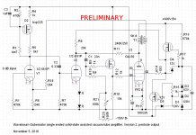
If you want we can make this GU50 amp as you suggested earlier - triode-connected at 350V/100mA with self-bias and 10K load which I think is just crazy only because of its astonishing efficiency....35W plate dissipation for 2.5W power we are talking here...!! - and optimized as much as you want and compare it to a 2A3 SE with fixed bias by means of a direct-coupled 6SN7 cathode follower and simply optimized to sound at its best.
45
Last edited:
Sorry gentlemen; I am not participating in such kind of discussions.
I have my humble opinion that the art and science of electronics design is proper optimization, and it works for me. If you have a scientific proof that fixed bias is preferable for Gu-50 class A single ended amp in triode mode, you are welcome to explain why, but please using simple technical words, without invitation to search in Google for articles written by your friends, no matter how you adore them. It is a technical forum, by the way...
I have my humble opinion that the art and science of electronics design is proper optimization, and it works for me. If you have a scientific proof that fixed bias is preferable for Gu-50 class A single ended amp in triode mode, you are welcome to explain why, but please using simple technical words, without invitation to search in Google for articles written by your friends, no matter how you adore them. It is a technical forum, by the way...
Well Wavebourn,
You are causing the discussion yourself.
Of course you may have your opinion on biasing, but that counts for everyone here OK?
You came up with adaptive bias.
I just wanted to tell you that one of the more creative minds wrote on this subject, and that it might be useful for you to take notice of that.
Science also means that we have an open eye for other people's efforts, right?
If you ask for "a scientific proof that fixed bias ....a.s.o." then start reading the posts properly in the first place.
Thank you for all the technical discussion, but back to my problem.
Power is not the final issue here, that's why my RH84 is connected in triode mode as I am willing to give up some efficiency for better sound quality. BTW I am using very efficient 96dB speakers.
Thank you Anatoliy, I am starting to understand the loadline now. So for the graph given, I should set a B+ that I want ( in the graph, that would be 350V ) and the idle current, then find the voltage bias required from the graph. The voltage -50V as given in the graph refers to the voltage measured between which points? g1 to ground or across the cathode resistor (as the calculation given implies)?
Correct me if I am wrong...but the following is how I should use the load line.
So basically, we can choose voltage/idle current combination that remains in the limits of the operating area of the tube as shown in the graph. eg: if we choose B+ of 400V and idle current of 80mA, then get the bias voltage required from the graph ie -65V, then calculate the cathode resistor from there...Rcathode = -65/.08=812.5ohm so we can use 820 ohms. Also from the graph, I think running at a higher Rload maintains the tube in a more linear regions of the tube function, hence your recommendation to do so.
I guess the same method applies to using the pentode load lines too? but the graphs are totally different for the pentodes. How do I determine the linear area for the pentodes graph?
Power is not the final issue here, that's why my RH84 is connected in triode mode as I am willing to give up some efficiency for better sound quality. BTW I am using very efficient 96dB speakers.
Thank you Anatoliy, I am starting to understand the loadline now. So for the graph given, I should set a B+ that I want ( in the graph, that would be 350V ) and the idle current, then find the voltage bias required from the graph. The voltage -50V as given in the graph refers to the voltage measured between which points? g1 to ground or across the cathode resistor (as the calculation given implies)?
Correct me if I am wrong...but the following is how I should use the load line.
So basically, we can choose voltage/idle current combination that remains in the limits of the operating area of the tube as shown in the graph. eg: if we choose B+ of 400V and idle current of 80mA, then get the bias voltage required from the graph ie -65V, then calculate the cathode resistor from there...Rcathode = -65/.08=812.5ohm so we can use 820 ohms.
Also from the graph, I think running at a higher Rload maintains the tube in a more linear regions of the tube function, hence your recommendation to do so. I guess the same method applies to using the pentode load lines too? but the graphs are totally different for the pentodes. How do I determine the linear area for the pentodes graph?
Yes, pentode and triode lines are drawn for the same purpose.
Since g1 is grounded through a grid leak resistor voltage drop on cathode bias resistor is actually applied between cathode and g1. 350V in such case is not a B+, it is anode-cathode voltage, so in order to find desired for the selected regime B+ you have to sum bias voltage, anode-cathode voltage, and a voltage drop on output transformer's primary winding.
It should be 400V in such case. I would recommend 2.4K primary OT.
If you want to go with pentode mode, you may use 700V B+ (it would be odd to remind that it is lethal!), and 250V between cathode and G2. You will need more expensive output transformer with higher primary impedance.
I keep reminding about danger because recently I myself stepped on such coincidence that I never could anticipate... Now I know that it is bad idea to drink coffee when working outside on a project, and it is a bad idea to reuse coffee mugs for paint thinners (especially antifreeze for acrylics), and it is a bad habit to finish coffee when finished smocking a cigarette...
Hey 45,
After a nights sleep I think we should not take Wavebourns words too literally.
I guess, as an experienced engineer, he knows perfectly well about biasing power stages.
However he should be a bit more careful in his remarks because the discussions which are triggered this way seem pretty much useless anyway.
Maybe in the meantime he checked Broskie's article on sliding bias...
 OT and personal attacks deleted. Yellow flags issued.
Attachments
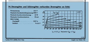
It seems that one alternative to make GU50 working as a triode with high anode voltage has been not presented yet. The pentode tube can also be connected as a triode by connecting screen and control grid together.
This connection forms GU50 as a "hi-mu" triode resembling much like 811A. In such connection the mu of the triode connected GU 50 is around 200...250. It requires some power to be driven and positive bias of some 7 to 8 volts when operated with 800 V anode voltage, but these are not too difficult to accomplish.
As many readers possibly know, GU50 is originally a German WW2 era tube namely LS50. It's datas can be found from the following site: http://www.mif.pg.gda.pl/cgi-bin/vs4.pl
At the last page of the data available from there (section 14. ), you can find this data.
I have built such SE-amplifier with GU50 and Edcor GXSE15-8-10k transformer and the results were very satisfying. The available output power was about 15 W.
Last edited:
It seems that one alternative to make GU50 working as a triode with high anode voltage has been not presented yet. The pentode tube can also be connected as a triode by connecting screen and control grid together.
Maybe because who started this 3d is newbie?
This connection forms GU50 as a "hi-mu" triode resembling much like 811A. In such connection the mu of the triode connected GU 50 is around 200...250. It requires some power to be driven and positive bias of some 7 to 8 volts when operated with 800 V anode voltage, but these are not too difficult to accomplish.
As many readers possibly know, GU50 is originally a German WW2 era tube namely LS50. It's datas can be found from the following site: http://www.mif.pg.gda.pl/cgi-bin/vs4.pl
At the last page of the data available from there (section 14. ), you can find this data.
I have built such SE-amplifier with GU50 and Edcor GXSE15-8-10k transformer and the results were very satisfying. The available output power was about 15 W.
Where is the advantage in comparison to the pentode connection? You still end up with 40-50 Kohms plate resistance I guess and same maximum plate dissipation (40W) with the additional complication of positive grid bias...!!
45
It seems that one alternative to make GU50 working as a triode with high anode voltage has been not presented yet. The pentode tube can also be connected as a triode by connecting screen and control grid together.
This connection forms GU50 as a "hi-mu" triode resembling much like 811A. In such connection the mu of the triode connected GU 50 is around 200...250. It requires some power to be driven and positive bias of some 7 to 8 volts when operated with 800 V anode voltage, but these are not too difficult to accomplish.
As many readers possibly know, GU50 is originally a German WW2 era tube namely LS50. It's datas can be found from the following site: http://www.mif.pg.gda.pl/cgi-bin/vs4.pl
At the last page of the data available from there (section 14. ), you can find this data.
I have built such SE-amplifier with GU50 and Edcor GXSE15-8-10k transformer and the results were very satisfying. The available output power was about 15 W.
This was what I heard of at first. If you look at my original post, this was the thing I was thinking of. A high voltage Triode mode for GU-50. Which i have been strongly discouraged from doing due to the dangers
This was what I heard of at first. If you look at my original post, this was the thing I was thinking of. A high voltage Triode mode for GU-50. Which i have been strongly discouraged from doing due to the dangers
If you don't afraid...
Attachments
- Status
- This old topic is closed. If you want to reopen this topic, contact a moderator using the "Report Post" button.
- Home
- Amplifiers
- Tubes / Valves
- GU-50 in Single-Ended Triode Configuration - What bias points?