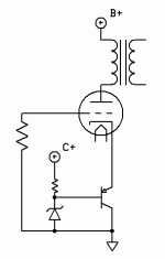
I'm looking for a tube bias mechanism that has a higher voltage drop and lower impedance than an LED string. Here's what I came up with. Initial testing shows lower overall distortion than LED bias, particularly for 3rd and higher harmonics, and way lower distortion than resistor + cap bias, but a bit of a rising frequency response. There is only a ~.5db rise from 40Hz to 15K, but it is audible as being a little bright. Any thoughts on viability, or issues that might crop up? Or what BJT to use? I might try a mosfet, too, to see if that's any better.
Attachments
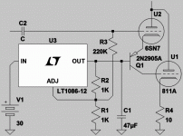
No clue if this could even work?
If U1 was a MOSFET instead of an 811:
Would need resistor from Q1 collector to
ground. To bleed constant current across
the threshold voltage of the MOSFET.
This would hold emitter of Q1 and 6SN7
loadline at the same constant current.
Probably nothing constant when driving
811 in A2. Pay $$$, take you chances.
6SN7 plate feedback enforces Mu.
Or so Triodlington theory would have it...
R1 R2 might could be pre-amp filaments?
Assuming no requirement to elevate...
Then again, might be better a pot.
Attachments
Last edited:
If loudspeaker was a simple resistor, I could see the logic in that.
Depends how, where, and why you measure THD.
Triode makes low THD with real load voltage feedback to plate.
Current feedback from cathode is a stab in the dark guestimate
whenever load impedance is electromechanical moving target.
Current mode damps no energy stored in mechanical resonance,
so am not fallin' for oversimplified Ampere turns reasoning either...
6SN7 plate makes for Mu in example above, R4 is mostly hidden
by the collector of Q1. Before anyone points out the conflicting
fact that I too have drawn R4 an unbypassed cathode resistor.
Last edited:
Ahh, the "ignorance" defense...
"We don't know what the load is, so we can't tell if one thing or another is better!"
So wait, why was the question asked in the first place?!
But there is something useful that we CAN use. It's called logic. You don't have to take it off with your shoes when you step inside the forum, you know.
It's reasonable to assume a loudspeaker is a linear element. A very complex one, but still linear. You increase the voltage (or current) to the speaker, it gets louder. Frequency has absolutely nothing to do with it. If it's linear, and if it works at one frequency, then it will work at all frequencies, simultaneously. That's all that's needed.
Since a loudspeaker is a linear element, it is true, in all cases, that if you reduce the distortion of the signal source, you WILL reduce the distortion at the output.
This isn't rocket science.
Tim
I get lower THD with a resistor.
I don't.
What's the distortion with a zener string I wonder? I have 3 amplifiers with LED cathode loads and want to try zeners on one of them.
Sometimes I wonder if we aren't just creating another regulated power supply underneath the cathode, but if it's good and simple, there are benefits. I am very interested in this direction.
I found, with LED's as cathode loads, an extended freq response both up high and down low, maybe that's why you think your cct may be a bit "bright", because you are hearing high freq detail you didn't hear before? Just a thought...
Sala's shunt section of his DC shunt supply might be a good candidate for this task, but still has the difficulty of fine-tuning the required voltage. Maybe you could get some ideas from that schem.
Last edited:
Yes creating regulated virtual ground under the cathode,
thereby real ground becomes our fixed bias. Same exact
things, only completely different...
Zenier string under the cathode? I'd say stick with 5~6V
types, as those have the most stable tempco... You need
bleed some extra milliamps through them to assure they do
not operate on the knee of the curve.
Also nothing wrong wit Crusher's emitter follwer, cept HF
bypass might be a good upgrade as previously noted...
Zeniers supposed to be white noise generators, probably
true. Yet strange I have never encountered a situation
where I actually been able to hear that effect...
Another way to fix cathode bias voltage is from above...
I call 3rd Leg Shunt... Someone suggested shunt reg?
Now here we got an "advantage?" that it pulls constant
current from the power supply. Wasteful, but probably
has sonic advantages. This is audio, I can claim any
insane thing...
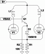
You now ask why with Schottky and R2? To keep the
BJT always turned on, no matter what... Schottky has
no such reverse recovery glitch, much more like glass.
If a tube turns on harder than expected, this will save
our bacon when things go back to normal.
R1 is selected to fix cathode bias at maximum current,
rather than the usual idle minimum... Tail current now
is constant, so all same-same here anyway.
Eliminate V2 & L2, you would have SE.
Add L2 to collector of Q1, you have SEPP.
Lots of silly ways to abuse this circuit.
Attachments
Last edited:
Yes, good circuits. Either should hold Zenier current
fairly constant, and dump the remainder around it...
Resistance across VBE or VGS threshold sets CCZ.
You still have to throw some extra current at it.
So Zenier never on the knee, and BJT never off.
If the tubes expect ever to approach cutoff, a
bleed resistor to B+ should be provided.
fairly constant, and dump the remainder around it...
Resistance across VBE or VGS threshold sets CCZ.
You still have to throw some extra current at it.
So Zenier never on the knee, and BJT never off.
If the tubes expect ever to approach cutoff, a
bleed resistor to B+ should be provided.
I don't actually know if that would solve your rising response issue?

It seems that the circuit works fine, and the rising frequency response is from a cheap OPT, or maybe a cheap tube, and not the bias method.
Here's the circuit I'm using it for -- the bias is set with an LED. Mu is close to 40, rp is ~3500, and grid current seems to start at about half a volt. Thus, in order to get a decent bias, I needed an LED with 3V or more Vf, but I couldn't find one with a low enough Z. Most are in the 30 to 40R range, and multiplied by mu, it drove rp way too high. Anyhow, this seems to work well. Definitely worth playing with.
An externally hosted image should be here but it was not working when we last tested it.
If you remove that cap, you won't have any transient issues.
I use saturation in the gate driver, upper right corner:
http://myweb.msoe.edu/williamstm/Class_D_Amp_Schematic.pdf
The CCSs Q5 and Q6 are biased for 80mA nominal, yet supply current in operation is a paltry 10mA. It comes out of saturation automatically in maybe 20 nanoseconds. You can safely assume transistors are faster than tubes.
Tim
Not saturation, but base minority carrier storage in cutoff.
Removing LED cap isn't going to prevent that in any way.
Your MOSFETs Q7 and Q8 are drawn outside orientation for
common gates, you intend that way? If this is switcher it
might make sense.. If this is a linear follower, I'm not sure
how you deal with rising Miller at such low drain voltage.
I'm not saying it doesn't work, only the schematic is not
revealing the theory of operation. What purpose is L1?
Maybe you could point me to a solid state thread about
that circuit?
Last edited:
- Status
- This old topic is closed. If you want to reopen this topic, contact a moderator using the "Report Post" button.
- Home
- Amplifiers
- Tubes / Valves
- BJT Bias?


