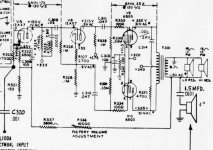
I have a PP 6BQ5 amp from a Hammond L-101 which I want to modify for general purpose use. The PA section looks to be a fairly conventional PP Pentode mode design with GNF taken back to the VAS cathode. The factory volume control is a nice feature as it will allow me to easily play with different levels of gNFB.

The one thing that is different is C310 and R325 which are in parallel with the plate resistor of the VAS. I believe that this is there, at least in part, to limit the high frequency response to reduce "key click" in the output. It seems that one would want to remove it to provide full range output however I note that no compensation cap is included in the NFB loop. So the question is whether this might also serve to limit bandwidth for stability purposes. If so is it advisable to change the value rather than remove it so as to insure stability and yet increase bandwidth somewhat as well?
I also question the bias point for the VAS. That bias point is well down on the curves and it seems that there might be a better bias point in terms of linearity. Any thoughts on modifications there?
Attachments
That RC network is fairly important, and does affect the sound and stability of the amp. It 'slugs the dominant pole'. See SY's Red Light District design for a good description.
It is affected in great part by the output transformer characteristics. The idea is to throw a square wave input into the amp, observing the output. The RC network is adjusted to maximize rise time of the square wave while also limiting the overshoot/ringing. Try at 1 kHz and 10 kHz. I can try to dig up some example square waves of poor / optimized if you aren't sure what you're looking for.
It is affected in great part by the output transformer characteristics. The idea is to throw a square wave input into the amp, observing the output. The RC network is adjusted to maximize rise time of the square wave while also limiting the overshoot/ringing. Try at 1 kHz and 10 kHz. I can try to dig up some example square waves of poor / optimized if you aren't sure what you're looking for.
Thanks. Unfortunately I don't have a siggy (well I do have an rf one but that is no help) or a scope  The first step I suppose would be to recap and then check the response. I think I remember finding a web site some time ago where they mod'ed these to restore the key click that was engineered out so I think I will hunt that up too to see if it can provide a feel for things.
Ah, just found it. They recommend removing C310 and C314 so maybe it is still stable like that. As I look at it again C314 might be the most important one for bandwidth limitation. It seems like removing that one should be no problem at all.
http://www.gietek.me.uk/html/keyclick.html
The first step I suppose would be to recap and then check the response. I think I remember finding a web site some time ago where they mod'ed these to restore the key click that was engineered out so I think I will hunt that up too to see if it can provide a feel for things.Ah, just found it. They recommend removing C310 and C314 so maybe it is still stable like that. As I look at it again C314 might be the most important one for bandwidth limitation. It seems like removing that one should be no problem at all.
http://www.gietek.me.uk/html/keyclick.html
Last edited:
Slugging dominant pole, is slew limited equivalent to clipping.
Best this happens as far above audio as possible. I forget now
who (maybe it was Nelson Pass, or Bob Cordell?) proposed the
example of 18KHz+19KHz sines at the same time. To explain why
slew might want 100Khz cutoff or more to avoid intermodulation.
On those occasions when both are rising or falling together...
I'm not saying it isn't the right thing to do. Every time there is
a loop, gain will have to be gently rolled off by a single pole to
less than unity. Well before all cumulative phase shift of other
poles (including unintended parasitics) make an oscillator of it.
I don't know that 100KHz cutoff is realistic when wound iron is
involved? But you still want to be shooting as far above 20KHz
as your transformer's parasitic phase shifts will allow. Aiming
high is the point I'm really trying to make here....
Remember the slug does not simply attenuate above its cutoff
frequency, but also distorts the leading and trailing edges into
a triangle wave... Like I said, its a form of clipping.
Last edited:
Thanks. Unfortunately I don't have a siggy (well I do have an rf one but that is no help) or a scope
Ah, just found it. They recommend removing C310 and C314 so maybe it is still stable like that. As I look at it again C314 might be the most important one for bandwidth limitation. It seems like removing that one should be no problem at all.
Modifying Hammond L100 - Keyclick
I think C310 might make a bigger difference than C314. C314 may be there due to the leakage inductance of the OPT and seems to introduce a pole > 20 KHz. C310 on the other hand starts shifting the VAS plate load at a few KHz.
gotta love those 12AX7... it's an amplifier... it's a voltage divider...
Michael
- Status
- This old topic is closed. If you want to reopen this topic, contact a moderator using the "Report Post" button.