I have been fumbling around in the old shed building a power supply setup for testing purposes.
Could you have a look at what I have & see if I have missed anything or will have any problems with things by the way I have set things up.
I will attach a picture of what I have.
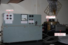
Basically I found a power transformer rated at 250VA with a 850-0-850 centre tap HT output which I will limit via a Variac to around 450V maximum output due to the Voltage meter I have at this stage.
I wanted to be able to adjust the HT without altering the heater voltages on either the Rectifier Valves or the others.
So instead of using these outputs from the main power transformer I fitted a 6V-7A transformer in the case as well for the heater supply voltages & have another small 0-6V 6A Variac for the 5V Rectifier valve filaments.
Everything is Fused & with indicator lights & switches, the HT output will run to another Plastic box which will be be Fused again with the appropriate high voltage switches & connecting blocks etc. The centre tap --ground connection will also run to the external plastic box & then to the test chassis etc, the main PS case is also grounded.
Have I missed anything or have any obvious erros etc?
It all appears to be working ok but I may have missed something.
Cheers.
Could you have a look at what I have & see if I have missed anything or will have any problems with things by the way I have set things up.
I will attach a picture of what I have.
Basically I found a power transformer rated at 250VA with a 850-0-850 centre tap HT output which I will limit via a Variac to around 450V maximum output due to the Voltage meter I have at this stage.
I wanted to be able to adjust the HT without altering the heater voltages on either the Rectifier Valves or the others.
So instead of using these outputs from the main power transformer I fitted a 6V-7A transformer in the case as well for the heater supply voltages & have another small 0-6V 6A Variac for the 5V Rectifier valve filaments.
Everything is Fused & with indicator lights & switches, the HT output will run to another Plastic box which will be be Fused again with the appropriate high voltage switches & connecting blocks etc. The centre tap --ground connection will also run to the external plastic box & then to the test chassis etc, the main PS case is also grounded.
Have I missed anything or have any obvious erros etc?
It all appears to be working ok but I may have missed something.
Cheers.
Attachments
Last edited:
If I were building a power supply for testing tube amplifiers, either for servicing old or building new, I would meter the output for both high voltage and current. I like analog meter movements because I'm old school. I would also include an adjustable negative bias supply of at least 0-75 volts. And up to minus 150 volts (or more) if planning to use 845s or GM70s. This would also be metered for both voltage and current with around a 50mA capacity. The DC output, (assuming yours is) need not be regulated for basic testing since this complicates matters and is not really necessary.I have been fumbling around in the old shed building a power supply setup for testing purposes.
Have I missed anything or have any obvious erros etc?
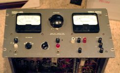
I'm not sure why you need an intermediate plastic box unless it's because there is insufficient space in the main supply box or panel. In my shop I have several Kepco power supplies like the one pictured below. They happen to be regulated, but they were cheap when I got them.
Attachments
HollowState,
Thanks for the reply, yes I have to add an amp meter to the output, I only have one that reads up to 20A here at the moment which is far to big to get a good reading. I have to buy a suitable meter, I also like analog movements as well.
The HT output from this unit is AC as I want to be able to test various things with rectifier valves etc, this is basically for Guitar amps only so I would like to test a few recitifier valves etc with it so I left it with an AC ouput for that reason.
Same with the negative voltage supply, again I was going to get this after the rectifier valves etc.
The intermediate box is more for being able to work with several different small test chassis, so I can just connect & disconnect at the box away from the main power supply case.
I have made up a circuit so I can load & unload Rectifier valves to have a closer look at the voltage dip produced, from part load to full load, this small intermediate box also has this circuit inside.
Thanks again for the reply
Cheers
Last edited:
- Status
- This old topic is closed. If you want to reopen this topic, contact a moderator using the "Report Post" button.