I'm happy to help if I can!
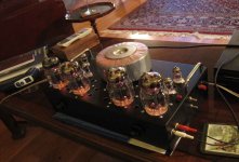
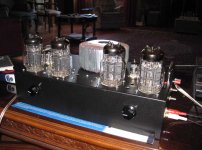
Here's a photo of my amp:
The toroid on top is for the HT supplies for the output tubes; it's a Hammond 182P117, with two 117V, 2.67A secondaries. I put the other transformers underneath in
the chassis; a Hammond 182S12 which has two 12V, 9.38A secondaries, for the 6C33C heaters, and a smaller Hammond 182L6 for the rest of the heaters. All three are concentrically mounted.
Oh yes, one more thing occurs to me; I strongly recommend adding lifting handles, as Tim Mellow did! It makes it much easier to pick up!
Chris
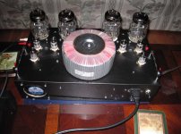
Attachments
Chris:
Very sharp.
Gave some thought to your post re tube PS, and I agree. As much as I'd like to go with a hybrid bridge, I don't know that it would be worth the trouble and expense. As far as I can figure, the current requirements pretty much demand either seperate trafos (or at least seperate secondaries) - and lots of 6d22s pairs.
Maybe I'm wrong - but I prefer "overbuild and running just above idle" to "Honey - where's the fire extinguisher?"
All those tubes would look pretty cool, though...")
Sincere thanks for all the info you've provided.
Side note: What's your spacing for the 6c33cs? Any overheating issues?
Very sharp.
Gave some thought to your post re tube PS, and I agree. As much as I'd like to go with a hybrid bridge, I don't know that it would be worth the trouble and expense. As far as I can figure, the current requirements pretty much demand either seperate trafos (or at least seperate secondaries) - and lots of 6d22s pairs.
Maybe I'm wrong - but I prefer "overbuild and running just above idle" to "Honey - where's the fire extinguisher?"
All those tubes would look pretty cool, though...
Sincere thanks for all the info you've provided.
Side note: What's your spacing for the 6c33cs? Any overheating issues?
It looks like Tim Mellow's pin numbering scheme for the 6C33C assumes you take the anode to be pin 1, and then count round from there. The seven pins on the 6C33C are at equal angular spacing, so there is no obvious choice for which should be called pin 1. The only distinguishing feature is that the anode pin is thicker than all the others, so calling it pin 1 could be considered natural, I suppose. But anyway, since his schematic doesn't indicate the pin connections for the two heaters, you need the full data sheet to get that information, so its probably best to stick with their numbering convention.
Chris
Hey Chris thanks but yes I agree the data sheets are clear a 6c33 tube does have a specific socket number count and the anode is number 4 so I think regardless of what Tims schema says its incorrect and all should know to follow the actual datasheets provided in this thread and that the thick pin is number 4.
For N1, I used a 65V 0.7mA neon lamp, type A9A by Chicago Miniature. Available from Mouser for 32 cents.
Any small neon lamp is probably fine.
For N2, by the way, I'm using an A81-C90X gas discharge tube made by EPCOS. Again, available from Mouser, for about $2.00.
thx again Chris, these are the ones i have as well but was mostly not sure if the t2 65v i have was the proper one. should have mine up and running by tomorrow
Another little issue I see and as usual in this thread until the rest of us get our amps running we will have to defer to Chris but the T2 transformer shows no CT on either secondary so you can't be tying V4's pins to ground unless you use resistors or have a CT and the same goes for the V5 winding for the lifting voltage. you either need resistors or a CT. AM I missing something? Are the dual 6.3v heaters in each section of the 6C33's acting as the CT?
Open to correction if I am wrong. Thx
but the T2 transformer shows no CT on either secondary so you can't be tying V4's pins to ground unless you use resistors or have a CT and the same goes for the V5 winding for the lifting voltage. you either need resistors or a CT. AM I missing something? Are the dual 6.3v heaters in each section of the 6C33's acting as the CT?Open to correction if I am wrong. Thx
Last edited:
The 182S12 Hammond transformer I'm using for T2 has two separate 12V secondary windings, so I use one for the two V4 tubes (each with their 6.3V filaments in series), and one for the V5 tubes (again, each series connected). I'm away travelling right now, and I can't recall exactly how I tied the V4 to zero, and V5 to -150V. I suspect I just picked the tubes of one channel, and tied the centre points of that pair. I doubt that it matters very much, as long as the V4 heaters are essentially at zero, and the V5's at -150V. I don't think hum is an issue on the output tubes. I can check the details when I get back next Wednesday.
I did, by the way, use DC for the heaters of the V1 tubes. I don't know how much difference, if any, that makes, since I didn't try with AC first.
About the spacing, I can't answer that precisely right now either, I'm afraid, until I get back. The amp certainly runs quite warm, but nothing outrageous, I think.
Chris
...and another question for Chris (as if he doesn't have enough of them on his plate already...): T1 appears to connect directly to the AC mains, outside of the mains switch, and would be powered up whenever the amp is plugged in - meaning V1-V3 heaters are always on. Am I reading this incorrectly?
No rush for an answer, sir - it can wait until you get back. I've still got a bunch of stuff to buy before I can get started, anyway...
): T1 appears to connect directly to the AC mains, outside of the mains switch, and would be powered up whenever the amp is plugged in - meaning V1-V3 heaters are always on. Am I reading this incorrectly?No rush for an answer, sir - it can wait until you get back. I've still got a bunch of stuff to buy before I can get started, anyway...
Indeed, S1 in the schematic is just a standby switch, and there is no overall on/off switch depicted. You can either add in another switch that turns power to the whole thing on and off, or else just connect T1 to the switched side of S1, which is what I do, since I can't really see the point of the standby option.
Chris
Chris
Hey Joe, I was wondering that same thing. No switch on T1, just that relay. I figured (without thinking about it too much) that the relay had some kind of start coming from the main power switch.
Edit, we must have been typing at the same time Chris. Thanks, that makes sense.
Edit, we must have been typing at the same time Chris. Thanks, that makes sense.
...and another question for Chris (as if he doesn't have enough of them on his plate already...
No rush for an answer, sir - it can wait until you get back. I've still got a bunch of stuff to buy before I can get started, anyway...
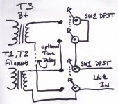
Thinking about wiring up the amp this way....from a file i found on the net long ago....faded now so i penned it.
Looking at this now.... time delay is useless I guess.....oh well
Darrell
Attachments
Last edited:
Hey Joe, I was wondering that same thing. No switch on T1, just that relay. I figured (without thinking about it too much) that the relay had some kind of start coming from the main power switch.
Edit, we must have been typing at the same time Chris. Thanks, that makes sense.
djn: If you're refering to N3, I'm reading that as a neon lamp. I'm not seeing a relay in the schem. Good idea, though - there are time delay relays boards available on EBay that fire up the HT 12-30 sec after the heater trafo powers up. Don't know anything about these units in particular, but it's an idea...
Power Supply Delay Action Board 300B 2A3 KT88 tube amp - eBay (item 160482877646 end time Oct-18-10 17:28:00 PDT)
Chris: As always, thanks.

Keeping T1 powered helps avoid any issues with the outputs coming up before the drivers - but I wonder if there are any long-term problems with keeping the filaments powered continuously... ?
I'm sure I'll have many more questions before this is done...

Chris: As always, thanks.
Keeping T1 powered helps avoid any issues with the outputs coming up before the drivers - but I wonder if there are any long-term problems with keeping the filaments powered continuously... ?
I'm sure I'll have many more questions before this is done...
I think just one switch, which turns everything on and off simultaneously, is fine; that's what I am doing. I forget the precise timings I measured for the heating up of the tubes, but it was something like 15-20 seconds for the EF86 drivers, and more than 30 seconds before the output tubes started conducting. So there is plenty of safety margin.
I don't think there is any good reason for keeping the filaments of the input and driver tubes running for long periods when the amp is not in use.
Chris
I don't think there is any good reason for keeping the filaments of the input and driver tubes running for long periods when the amp is not in use.
Chris
agreed Chris. In my GM70 (which I hope to assemble very soon) I am using an industrial delay that fits into an octal socket. I can then set the time with a knob on top from 2 sec. to 2 min. Or something close to that. Even though I am using tube rectifiers that take 30sec to warm up, the GM70 needs a bit more time than that.
Hi Brad,
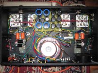
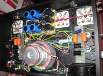
Here are a few pics, two from below and two from above. I'm afraid my wiring is a bit of a bird's nest, although functional.
The two transformers under the chassis are for the heaters; 6C33C's powered by the larger one, and the rest by the smaller one. The monster above the chassis is for the HT supplies.
Chris
Attachments
The 182S12 Hammond transformer I'm using for T2 has two separate 12V secondary windings, so I use one for the two V4 tubes (each with their 6.3V filaments in series), and one for the V5 tubes (again, each series connected). I'm away travelling right now, and I can't recall exactly how I tied the V4 to zero, and V5 to -150V. I suspect I just picked the tubes of one channel, and tied the centre points of that pair.
Hey Chris good to see you back. did you get a chance to check on how you tied the center taps on the output tubes to ground? to me it seems the schematic is incorrect that the CT point on the seperate tube heaters were tied that way but maybe I am wrong, would not be a first
Thx again in advance!
Just FWIW: the filaments of the power tubes do not have to be grounded for the amp to be quiet. I have found that a good electrostatic shield is handy though. That will win you more than any grounds in the filament circuit itself.
You can also run this tube on 12V by putting the filaments (there are 2 per tube) in series. That can make the wiring go a little easier. FWIW its a good idea to use an 800 degree silver solder on the tube connections!
Another thing you want to think about is the diameter of the hole for the socket. You want it to be a little on the large side so air can move by the tube. I've installed a circle of holes around the socket for the same reason. Finally, a set of Teflon washers between the chassis and the socket is not a bad idea- by lowering the socket you open up a gap for air flow.
- Home
- Amplifiers
- Tubes / Valves
- OTL designed by Tim Mellow with 4 6C33C?