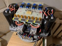
Thank you for the link, I already ordered the JCCON-s, I'll let you know my experience with them. They fit nicely in my chassis and even if real-life spec is lower than stated, I still have a healthy reserve from 2200uF onto 1700uF (the latter is in the original design). I'll probably put some really high-quality film type on each and then that's it.
I'll apply regulation too, I thought of elevating the GND to a virtual GND with diodes and then the top of the voltage fluctuation can fit into the range of this floating stabilizer easily. I hope it will work")
I'll apply regulation too, I thought of elevating the GND to a virtual GND with diodes and then the top of the voltage fluctuation can fit into the range of this floating stabilizer easily. I hope it will work
having the filter caps in series also have their esr's in series, i suspect the parts that were available to Tim Mellows those times was the reason for it, but 250volt rated caps are available and easy to acquire.
Good point.. what I'm thinking of is: resistance in series doesn't limit current flowing through them so it stays the same (voltage drop is bigger however, but if we approach low-ESR with the mindset to get more instantaneous current out of the capacitors for a short transient then voltage is a less-issue or let's say easier to fix.. but I might be wrong..
). On the other hand, parallel-placed electrolytics with decreasing common ESR (the block seen as 1 cap) help getting the juice out of them quicker at the same voltage compared to 1 cap.This issue with MANY parallel caps I see is when they fail: caps usually fail like making a short and if that happens, the whole capacitor block will be shorted and the excess current needs to be handled. Perhaps by a fuse
and if 1 fuse is enough or not is a good question, maybe yes (on the primary side, at the AC inlet, for the whole device) or maybe an additional one would serve better.. or transistor, another diode.. 3rd thought from me: actually, I wouldn't bother that much regarding ESR for a Class-A amplifier: the idle current draw is intensely loading the PSU part all the time, so caps, diodes, transformer is feeding pretty much current need.. and only about the very top 10% of the maximum available power is fluctuating (this increases when the amp goes into Class AB but still remains within about ~40% fluctuation vs. ~60% constant current), so in my opinion serving transients in music don't make such a huge impact on the PSU than in case of Class-D, where in idle there's barely some minimal current flowing but as musical signal changes rapidly, the load on the whole PSU also changes like crazy, causing heavy impact here with huge transients depending on music.
That's why I think Tim didn't have any issues with series caps, besides the maybe valid fact that at that time there were no suitable 1-cap available on the market, or at least not in audio-quality like the ELNA-s mentioned by him.
Just guessing / thinking loud, feel free to correct me.
I've not followed the recent discussions on this thread, so apologies if this is going over ground that was already discussed. However, I just wanted to point out that the Tim Mellow OTL is only operating in class A mode at very low output power levels. Above a couple of hundred milliwatts, it will be firmly in class AB. So the current demand on the power supply will be swinging by a lot, if it is operating at high power outputs. For example, the 200mA quiescent current draw of the output section rises to a peak of 2.5A at 25watts output power into an 8ohm load.3rd thought from me: actually, I wouldn't bother that much regarding ESR for a Class-A amplifier: the idle current draw is intensely loading the PSU part all the time, so caps, diodes, transformer is feeding pretty much current need.. and only about the very top 10% of the maximum available power is fluctuating (this increases when the amp goes into Class AB but still remains within about ~40% fluctuation vs. ~60% constant current), so in my opinion serving transients in music don't make such a huge impact on the PSU than in case of Class-D, where in idle there's barely some minimal current flowing but as musical signal changes rapidly, the load on the whole PSU also changes like crazy, causing heavy impact here with huge transients depending on music.
That's why I think Tim didn't have any issues with series caps, besides the maybe valid fact that at that time there were no suitable 1-cap available on the market, or at least not in audio-quality like the ELNA-s mentioned by him.
Just guessing / thinking loud, feel free to correct me.
And that is just for one channel. In Tim Mellow's design both channels use the same power supply. So if both channels are outputting 25W, the total of 400mA quiescent current for the output stages can increase to 5A at the peak of the audio waveform.I've not followed the recent discussions on this thread, so apologies if this is going over ground that was already discussed. However, I just wanted to point out that the Tim Mellow OTL is only operating in class A mode at very low output power levels. Above a couple of hundred milliwatts, it will be firmly in class AB. So the current demand on the power supply will be swinging by a lot, if it is operating at high power outputs. For example, the 200mA quiescent current draw of the output section rises to a peak of 2.5A at 25watts output power into an 8ohm load.
Thanks for the explanation. Well, I wasn't sure if the PSU in the original article was purposed for 1 side, or stereo.. (driving 2 amp circuits in fact) so I made for the 2 amplifier parts 2 separate PSU sections too, with a 400VA toroidal transformer each. At least they will run in a relaxed mode then and even better serve the transients. I hope a good result at least.
I'm probably giving up the issue with the top plate, I just have an idea how to mask/hide that long carved line on the surface. Can't wait beginning with soldering and finally hear the thing.
I'm probably giving up the issue with the top plate, I just have an idea how to mask/hide that long carved line on the surface. Can't wait beginning with soldering and finally hear the thing.
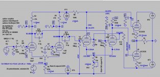
Finally I came to my final conclusion (and need) regarding input sensitivity, using pots or not and re-read all of these comments about reducing gain (of input stage) via cathode resistors + increasing feedback too (to some extent).To reduce gain in front LTP just insert cathode resistor of equal value to each leg with out affect the anode voltage that set the bias of entire stage. When the gain is reduced you need to increase gNFB to maintenance damping factor is also a good way to check which damping factor is best for your speaker.
12ax7 ltp stage has a max. gain of 20, it's possible to reduce it to unity with 20k cathode resistor.
- I don't use pot at all, all inputs would be direct inputs (preamp funcionality is in the DAC with 2Vrms/4Vrms output on RCA/XLR respectively)
- I try to shield everything as much as I can.. hoping the best here for a sufficiently low basic noise level
- I'd leave feedback there, where it is (according to the original schematics) since I have no pot -> no feedback change with pot impedance change, it's fixed so I think the original place for feedback is right so
- Therefore, I would NOT swap V1 to V2 parirings but staying with the original circuit here too
- XLR normal/inverted signals would go directly just before C1/C2 capacitors as suggested by original article
So, to put is simple: I would go with the original schematics, but without pot and with decreased sensitivity (as long as I can maintain stability & good DF).
Being on a learning path with circuits, can you help me with the following ? I learned you already go this route too, so:
- I'd use 20k cathode resistors on the input tubes just like you're using (if I'm right)
- what value to use for the RV1-substituting fixed resistor in this case ?
- what value worked for you for R3, the feedback ?
- and finally, what are the input sensitivities you achieved now with these modifications ? (Just for me to know). For both RCA and XLR (although I'm mainly aiming for XLR).

Now a very different question (not directly related to Tim's OTL but could be): given the huge max volume levels of nowadays' DACs (2Vrsm/4Vrms), would a 2-stage OTL make sense ? With ECC99 (Ug=-4V/Ia=18mA) or 6SN7 (Ug=-8V/Ia=9mA) on the XLR inputs and acting also as drivers for the 6C33C tubes ? Either as a whole new design or keeping ideas from this one.
Because what I see now is that we have here a 500mV input sensitivity and with nowaday's DACs it seems like it's not needed at all, we're not in the old phono-world anymore (or at least I am not and if using LP ever again, I'd either separately amplify it to around 2V/4Vrms or simply use a modern one with 24/96 USB output, feeding my DAC... - my LP at the moment also has a TI Burr-Brown 16/44.1/48 inside, with USB and optical-out, works fine although hardcore high-end people would argue strongly against such.. )
Because what I see now is that we have here a 500mV input sensitivity and with nowaday's DACs it seems like it's not needed at all, we're not in the old phono-world anymore (or at least I am not and if using LP ever again, I'd either separately amplify it to around 2V/4Vrms or simply use a modern one with 24/96 USB output, feeding my DAC... - my LP at the moment also has a TI Burr-Brown 16/44.1/48 inside, with USB and optical-out, works fine although hardcore high-end people would argue strongly against such.. )
I recalled one asked if 12at7 can be used instead of 12ax7, presumely to reduce sensitively. Yes it reduces sensitively by 3X (0.5v-1.7v)
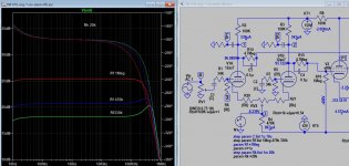
Change 100k plate resistors of 12ax7 to 47k, IM feedback/grid resistor to 470k. If you use other lower gain tube like 12au7 the sensitivity can be further reduced. DC servo may be not as good due to loss of gain, I don't know maybe offset is still acceptable if bias is adjust properly.
If you use 20k cathode resistor, it reduced the gain by X10 (same if 12at7), so you'll use 470k for nfb/grid resistor. RV1 (vol pot) can be fixed at 100k
Attachments
Last edited:
Thanks a lot. My bad, but I think your linked picture doesn't help me further at this stage, super confused, I worked and still stick to the schematics drawn and published in the article. That's the only one I can look at right now.
So to sum up, what would work for sure:
Did I understand you correctly ?
What would be the max. input voltage in this case ? (Approximately).
So to sum up, what would work for sure:
- Swap R3: 1M -> 470k
- Two NEW resistors between RV2 and the two cathodes: 20k (each)
- Swap R5, R6: 100k -> 47k (each)
Did I understand you correctly ?
What would be the max. input voltage in this case ? (Approximately).
As I understand from OP he probably can do tube rolling in future, now the prioity is get original working. Could add cathode resistor on demand using a switch with no other modifications. even tube rolling required a few changes in the resistor value. It would be wise to do AB test: A-original, B mods, but still need audio balance (voltage divider) to be able to compare. I can't do tube rolling in particular PCB as tube has no equivalence unless I change the driver schematic. My driver is on eyelet PCB hand wired (not printed) so there is not much limit as to what I can do. If you're doing development project like me you should build driver on PCB rather than hardwired into chassis (even point to point), replace one or both PCB is all you need.
Last edited:
I feel this amp has a lot of negative feed back applied already add more may cause instability or over damping. There is no one fix NFB would suit all your speakers, it may or may not work. I have a look at frequency responce, the current level of NFB has very high peak at 100k, add more feedback cause it to peak higher. You can compare the response when 20k cathode is used, no peak at all.
Last edited:
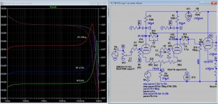
I hate to say but this is your option, right? Too much feedback can easily cause instability, that is general consensus esp. when it has a transformer in the circuit, the amount of feedback is very much limited. 12AX7 is considered low bandwidth, try to increase feedback is asking for trouble.
- Home
- Amplifiers
- Tubes / Valves
- OTL designed by Tim Mellow with 4 6C33C?