Hello,
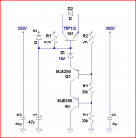
Before blowing stuff into little pieces, I'm going to ask before building... is the following regulator ok (nothing new here, it's a well known tubecad design) ? The only real change is the replacement of the TIP50 by a TIP152 (400V darlington with hfe of 200, see datasheet: http://www.datasheetcatalog.org/datasheet/mospec/TIP151.pdf ). The 40uF caps are mkp.
It will be placed after a 330-0-330, 85mA transformer and an EZ81, to provide 70mA@300VDC (headphones amplifier).
Thanks in advance for any comment.
Attachments
You're right. Under a 85m load, the xformer actually gave 415V. However, I'll add 100ohms resistors in serie with the plates of the EZ81 and that should drop quite a lot of voltage (there were none in the scope I've pulled it from). I'll also add a RC filter to get to 360V, whose value will depend on the actual voltages I'll get.
- Status
- This old topic is closed. If you want to reopen this topic, contact a moderator using the "Report Post" button.