For 12AU7/ECC82, I found only three options:
PCB Experimenter's board
http://www.diyaudio.com/forums/tubes-valves/21639-tube-buffer-using-12au7.html#post251585 Note: Take the 6N1P/6DJ8 schematic from post 1 and then modify that schematic to support 12AU7/ECC82 according to the directions in post 3.
Headphone amp (or hi-current preamp)
PCB Experimenter's board
http://www.diyaudio.com/forums/tubes-valves/21639-tube-buffer-using-12au7.html#post251585 Note: Take the 6N1P/6DJ8 schematic from post 1 and then modify that schematic to support 12AU7/ECC82 according to the directions in post 3.
Headphone amp (or hi-current preamp)
For 12AU7/ECC82, I found only three options:
PCB Experimenter's board
http://www.diyaudio.com/forums/tubes-valves/21639-tube-buffer-using-12au7.html#post251585 Note: Take the 6N1P/6DJ8 schematic from post 1 and then modify that schematic to support 12AU7/ECC82 according to the directions in post 3.
Headphone amp (or hi-current preamp)
thanks for your help!
Tube buffer with 6n3 for better sound !
Hi guys!
Instead of the proposed complete tube buffer schematic with 6n3 I would suggest this new improved schematic that provides better sound!")

Yes Viewed schemtic so little comment if you have one.
Enjoy!!
Cheers!
Hi guys!
Instead of the proposed complete tube buffer schematic with 6n3 I would suggest this new improved schematic that provides better sound!
Yes Viewed schemtic so little comment if you have one.
Enjoy!!
Cheers!
Attachments
Last edited:
What is the optimal DC operating voltage?
This buffer project is very prone to clipping, thus the audio input has to be attenuated abnormally to prevent clipping. I'm looking for a way to get ordinary line level signal through this tube buffer, without either attenuating or clipping. Help?
i do not think clipping is an issue here.....
assuming 2 volts rms max input....
that is about 6 volts peak to peak,
the circuit is a cathode follower...
and 6 volts peak to peak is quite small
compared to the 60 volts peak to peak available...
Has anyone noticed..?
On post #83 there was a schematic of a different tube based buffer presented.
Has anyone noticed that what is labeled as the earth ground on the voltage doubler is connected to the filament voltage?
I bought one of these and this is indeed how the board is laid out.
Anybody else think that this is a problem?
Well, I noticed that it does run a bit warm (especially the piping hot filament regulator), and it is more problematic (albeit more fun) than a discrete solid state project. However, the filaments are lit to approximately the right amount, a dim yet fire color orange (not rusty red, not yellow), so it does appear that at least the filament portion is in the ballpark.
Anybody else think that this is a problem?
no problem, filaments can be grounded to the psu ground at either positive or negative end of the filament dc supply...
Detailed of the Issue
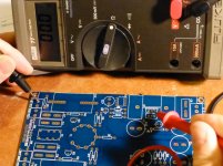
Thank you for the responses, but I believe that I need to be clearer about the issue.
In the attached photo I am probing from pin 2 on the regulator (the output) to the ground pin on the right input.
Note that the meter is reading zero ohms meaning, and I followed the traces to be sure, that, as shown in the schematic, the regulator output is shorted to ground.
Hence, I am not surprised that there was a response that the regulator runs very hot.
It's likely pumping out large amounts of current trying to drive ground to the filament voltage, although I am not sure what resistance it's working against
In fact, I am surprised that the circuit works at all if people are connecting ground to the signal input and output ports!
Are people not making those connections?
I have identified some judicious cutting and pasting that could be done to elevate the short and allow connection to the input/output grounds.
However, before posting that I would be interested in knowing if there is anyone out there that has an assembled board that might be willing to make some voltage measurements and see where the doubler and PCB ground potentials sit with respect to earth ground.
Anyone game?
Attachments
Regulator 2nd pin is grounded because its a fixed one regulator not a 317
But if you detected a short circuit may cause alarm because it is not going to deliver the normal voltages spected here if using a 7805 at least put a 7806 in there so the tube could last a bit more
Look at the pic the regulator ground was elevated so that could deliver a more common voltage to the heaters (but I would triple check the PCB for security)

A more acurate design but with 2 diodes instead of one, the upper pic also its miss calculated giving a lowish 5.6 -5.7 volts

But if you detected a short circuit may cause alarm because it is not going to deliver the normal voltages spected here if using a 7805 at least put a 7806 in there so the tube could last a bit more
Look at the pic the regulator ground was elevated so that could deliver a more common voltage to the heaters (but I would triple check the PCB for security)
A more acurate design but with 2 diodes instead of one, the upper pic also its miss calculated giving a lowish 5.6 -5.7 volts
Last edited:
There really is a problem!
Thank you maton00 for the regulator and diode idea.
That is clever and I will have to try it.
However, the seller got back to me and admitted that the PCB is laid out incorrectly.
He suggested a three cut and three jumper correction.
The pictures he sent are attached, but I am only able to see two cuts and three jumpers.
Anybody see the third cut?
Attachments


In regards to this schematic,
With the 4 transistors, there's a pair used for capmulti and there's a pair used for current limiter.
The circuit doesn't even seem to need a current limiter, and the limit that it has, seems to work too well.
So, which resistor value (6k8, 4k7, 33R, 330R) should be changed to allow enough current through the circuit to prevent clipping?
Would changing the 33R to 15R do it?
Better Photos
Here are what are some hopefully more visible pictures of the cutting and jumping the seller recommends to correct the PCB.
The red circuits outline the three trace cuts (one on the front and two on the back) and the three wire jumps (two in bare wire and one in an orange insulation all on the back).
Attachments


On mine, I drilled holes through the board directly underneath that heatsink (to remove heat pooling), tilted that one too-close cap away from the heatsink slightly and altered the reg to measured 6v output. That reduced some of the most basic difficulties.
That was not sufficient per audio quality; however, a 6n3p-E tube and a 14-0-14 transformer made it a lot more useful and quite nearly sufficient.
Untested: It may be possible to use schottky in the rectifier and voltage multiplier, for lower loss and higher resulting voltage, so that an ordinary 12-0-12 transformer can be effective.
After the slight voltage boost and better tube, the remaining trouble is headroom. The problem isn't as bad after the slight voltage boost, but still it lacks for headroom. I suspect that one or more resistor values may be off, per current (because insufficient).
P.S.
I changed the LED to fire-colored orange/amber 3mm flat top, which is quite attractive and allowed some room for air circulation about the tube. That actually helped drop the temp at the tube by a nice amount. Also, I had soldered the socket UP about 1.7mm extra to allow slightly more airflow. It doesn't run at scary temps anymore. I was able to use some 2C51 which are smaller size, without the too-hot temps problem.
Last edited:
got two kits wired up and ready for testing....
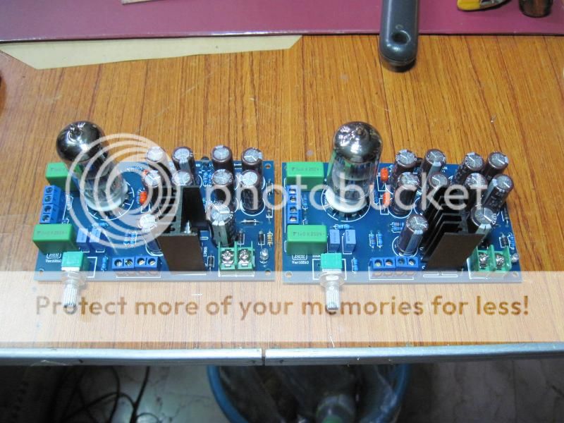
Hello everybody.
Nice gadget from China.
How does it sound?
Noise floor and 60Hz "hum"?
Stereo separation, detail, ambience...
Please, can you tell us what are the 220uF/50V caps diameter, the NP Caps 1uF and 470nF size?
Thanks a lot
Take a good hard look... I was going to buy myself one but after seeing this video I don't think so...
https://www.youtube.com/watch?v=N0WEBGm2f9s
https://www.youtube.com/watch?v=N0WEBGm2f9s
Odd situation there.
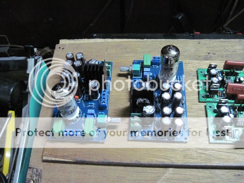
I received mine at December 2014 and assembled the 2 units with the original thermo ionic parts 6N3 and with GE 5670W. Although its not an amplifier its only a buffer, the active parts are working. I saw clearly the distortion fall while the heat climb on the different valves I tested when I plug the power to the units, with my Velleman PGSGU250 in FFT mode. However I never listen it play music, until now didn't fit in any project I start.
I remember a load of 10kOhms was the minimum acceptable to get an output with decent THD performance "<60db". It reaches 1Mhz frequency response.
No gain, worst channel separation and distortion is expected.


In each package I wrote the 2nd HD level at the same output voltage and load.

Cheers
PALUSE,
video I posted obviously says that there is only potentiometer in a circuit and all those caps, resistors and lamp are only for decoration purposes only. Your buffers look similar, element placement look very similar or even the same except signal ins and outs.
I was going to buy one like Yours, not the "Little Bear" from the video. Could You try to make it work or even perform a test similar to the video?
Thanks
Ok, I observe the schematic and its obvious that the input signal can travel directly to the output. I'll get the VR at 0 ohms in the path, a 470kOhms resistance, plus a 470 Ohms resistance and the decoupling caps at input and output; so a 1V signal will get around 0,5V at the output with that 470kOhms load. If we join the 47kOhms official input load at the buffer output then we should obtain near 0,1V.
I believe that some attenuation should be get in passive mode (-20db) with a 47kOhm load with the capacitors impedance ignored.
In reality we should get even more attenuation than -20db in passive mode.
Cheers.
I believe that some attenuation should be get in passive mode (-20db) with a 47kOhm load with the capacitors impedance ignored.
In reality we should get even more attenuation than -20db in passive mode.
An externally hosted image should be here but it was not working when we last tested it.
Cheers.
- Home
- Amplifiers
- Tubes / Valves
- 6N3 Tube Preamp with DC-DC converter