I've been thinking about making a small amplifier using a 12AU7 preamp, and an LM386 power amp. This is not Hi-Fi, but something I would like to use at work to power a pair of small speakers, either from the PC or MP3 player.
I was intrigued by this design for the front end using a 12AU7 running on 9VDC from a wall wart:http://www.beavisaudio.com/Projects/ValveCaster/MatsuminValveCaster.gif I was surprised you can run a 12AU7 with 9V on the plates.
Now this is intended for a guitar, so the gain might be too much for an MP3 player. Can anyone suggest ways to reduce the gain if this is the case? Can I eliminate the gain pot altogether since I will have a volume pot on the front of the LM386 amp? I'm planning on just using the typical LM386 circuit from the data sheet with a gain of 20.
Maybe there are better chip amps than the LM386 (higher fidelity) that also run off from 9VDC? I'm open to suggestions.
I'd like to build this into a small Hammond die-cast box, probably a "BB" size.
Any thoughts from the tube gurus? I'm open to suggestions.
Thanks in advance.
Glenn
Thanks, I'll give them a look.
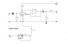
Maybe this is better:
http://diyaudioprojects.com/Solid/12AU7-IRF510-LM317-Headamp/12AU7-IRF510-Headphone-Amp-Schematic.png
It's for headphones, so maybe I'll just couple it to the LM386 for the power amp section.
Glenn
Maybe this is better:
http://diyaudioprojects.com/Solid/12AU7-IRF510-LM317-Headamp/12AU7-IRF510-Headphone-Amp-Schematic.png
It's for headphones, so maybe I'll just couple it to the LM386 for the power amp section.
Glenn
Thanks, I'll give them a look.
Maybe this is better:
http://diyaudioprojects.com/Solid/1...damp/12AU7-IRF510-Headphone-Amp-Schematic.png
It's for headphones, so maybe I'll just couple it to the LM386 for the power amp section.
Glenn
I used this into a small vellman amp 15W+15W. It works really well if you use bypass caps on the supply! If you use a wall wart it will hum badly. I used a laptop power supply and it sounds quite good for a mini system with Ipod.
")
Regards
M. Gregg
It is component dependant. I used metalized paper caps for the input! Also you will need to have an output mute at switch on / off, because it thumps on power off! Time power off so output off then power off timer! Power on then output on! Or have a separate switch for the power and pre sections! I used an "I tube" before this, the Itube is in the cupboard since switch on!
Last edited:
I'd build the amp only with the chip, because it doesn't need the tube as a voltage amplifier.
If you want to expiriment with the tube and simple circuitry you'd better take the schematics (sorry it's hv) from the tube's datasheet and use it as a voltage amplifier for an SE class A MOSFET or BJT.
If you want to expiriment with the tube and simple circuitry you'd better take the schematics (sorry it's hv) from the tube's datasheet and use it as a voltage amplifier for an SE class A MOSFET or BJT.
It's definitely NOT for guitar, I want to just power some small JBL bookshelf speakers. That's why I was afraid that the first schematic I posted just wouldn't do. It's really meant for overdrive/clipping for a guitar, and probably voiced for it as well.
I may build the headphone amp then and couple that to the LM386, thanks for the reply. Good to know about the caps and the mute switch also. I did say wall wart, but I know better than that. I have a nice clean 9V power supply that I built for my guitar pedals.
I really wanted this project to have a tube front end for the sound. Just an LM386 amp is too "normal" I've built enough Hi-voltage tube amps for both guitar and Hi-Fi use, I just wanted a nice little mini amp with a tube front end. Again, my goal isn't super HiFi, just something more as a conversation piece that I can use with my MP3 player at work.
Is there a better alternative to an LM386? An LM3886 is nice, but it requires 28v, and it's got a lot more power than I need.
Thanks everyone.
Glenn
I may build the headphone amp then and couple that to the LM386, thanks for the reply. Good to know about the caps and the mute switch also. I did say wall wart, but I know better than that. I have a nice clean 9V power supply that I built for my guitar pedals.
I really wanted this project to have a tube front end for the sound. Just an LM386 amp is too "normal"
I've built enough Hi-voltage tube amps for both guitar and Hi-Fi use, I just wanted a nice little mini amp with a tube front end. Again, my goal isn't super HiFi, just something more as a conversation piece that I can use with my MP3 player at work.Is there a better alternative to an LM386? An LM3886 is nice, but it requires 28v, and it's got a lot more power than I need.
Thanks everyone.
Glenn
Running a 12AU7 at 9V won't even be normal HiFi, let alone "super HiFi". As SY said, it is an effects unit. As you have now said, it is a conversation piece i.e. a piece of artwork, not engineering. Why not just use a diode/resistor network if you want distortion, or mount a non-functioning valve with LED underlights if you want pretty.
I've already agreed that the schematic in the first post is not good for what I'm looking to do. I was now focusing on the second schematic in post #4. Since this is a headphone amp, I would think it would have to be halfway decent to listen to. I'm just thinking of coupling that to some sort of small chip amp for a compact stereo amp that has a nice tube sounding front end to it. This approach also has the added benefit of being able to use it with a pair of headphones and bypassing the power amp section altogether.
Glenn
Glenn
But it still has far too low a supply voltage, so the only "tube sound" you will get is distortion. If you want to use a valve then you need 30-40V minimum; even then you will get some distortion. Valves don't magically wipe away "SS sound" - like any other component they either add/subtract very little (when used correctly) or add their own distortions (when used badly).
But it still has far too low a supply voltage, so the only "tube sound" you will get is distortion. If you want to use a valve then you need 30-40V minimum; even then you will get some distortion. Valves don't magically wipe away "SS sound" - like any other component they either add/subtract very little (when used correctly) or add their own distortions (when used badly).
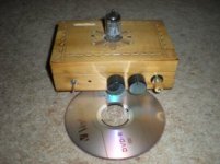
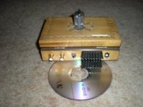
I know I thought the same thing so I built it! How can a tube run on such a low voltage. However in the link the guy refers to the tube being used in low voltage applications in the battery circuits in the military! Not with an inverter!
So I built the circuit out of curiosity and I have to say it sounds quite good even when amplified at party levels! OK it's not hifi, however it gives mini systems a run for their money! You can hear people breath as they sing and the wood on acoustic guitar!
Regards
M. Gregg
Last edited:
Thanks for the review, probably worth building since it's a pretty simple circuit.
I'll post pictures when I complete the prototype. Thanks for all the input everyone!
EDIT:
Here's the full explanation of the circuit http://diyaudioprojects.com/Solid/12AU7-IRF510-LM317-Headamp/
I'll post pictures when I complete the prototype. Thanks for all the input everyone!
EDIT:
Here's the full explanation of the circuit http://diyaudioprojects.com/Solid/12AU7-IRF510-LM317-Headamp/
Member
Joined 2009
Paid Member
Ready-made for T-amp
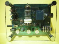
There is a $20 pre-build buffer board with 12AU7 intended for Tripath amps so it may work with LM as well. I have one with TA2020 and it does make a difference ('rounding' the sound). It's fed off 12V but the tube gets 43V (3ma) which is a more realistic level. You can see it at
Special for Tripath! 12AU7 Buffer Amp for smooth sound - eBay (item 260658637265 end time Sep-30-10 20:25:26 PDT)
- Status
- This old topic is closed. If you want to reopen this topic, contact a moderator using the "Report Post" button.
- Home
- Amplifiers
- Tubes / Valves
- Small Tube/SS hybrid amplifier design 9V