It will depend on the resistance at the other end of the line going to the right. The plate load contribution will be rp + (mu + 1)Rk, with rp and mu being the plate resistance and amplification factor for the top tube. This will be effectively in parallel with whatever load is off to the right.
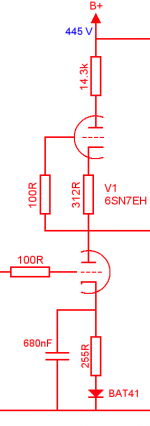
Both triodes are 6SN7. Data quotes rp as 6.7k at 90V / 10mA and 7.7k at 250V / 9mA. Both triodes have about 150V across them with 9.6mA, so I'll guestimate that the rp is about 7.5 k.
mu = 20
rp = 7500
rk = 312 (the bottom triode has a diode in there, but the voltage drop is equal to this resistance)
rp + (mu + 1)Rk = 7500 + (20 + 1) x 312 = 14052
Now I must have misunderstood something, this can't be - with 14k plate load the DC conditions don't add up; at 9.6mA the voltage drop measured is about 150V, but calculated it's only 134.9V - and I've understood that this kind of arrangement has a higher AC load than DC load, at least it should be equal, right?
Where did I go wrong?
with 14k plate load the DC conditions don't add up; at 9.6mA the voltage drop measured is about 150V, but calculated it's only 134.9V - and I've understood that this kind of arrangement has a higher AC load than DC load, at least it should be equal, right?
Where did I go wrong?
It's an AC load, not a DC load. But you've calculated it correctly; a triode run that way is an amazingly poor CCS. That's why people have added extra bits to run mu or beta followers. Or used MOSFETs...
hey-Hey!!!,
One solution is to deliver a voltage reference to allow a significantly higher cathode R OTO 5-6k Ohms, which when multiplied by the mu of ~20 delivers some significant plate resistance. Or get a higher mu tube, or both, and/or stack a pentode on top of the triode to make a tube cascode...but that will take two biasing voltages...")
cheers,
Douglas
One solution is to deliver a voltage reference to allow a significantly higher cathode R OTO 5-6k Ohms, which when multiplied by the mu of ~20 delivers some significant plate resistance. Or get a higher mu tube, or both, and/or stack a pentode on top of the triode to make a tube cascode...but that will take two biasing voltages...
cheers,
Douglas
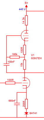
Same formula as before. All you have done is separate the AC and DC arrangements for the upper triode. Rk is now 10.1K.
Yes, but that increases the source resistance. It's still mediocre, but 200k is better than 14k, and is close enough to a true CCS (in relation to the rp of the lower tube) that the gain will be very close to mu and the distortion very close to minimum.
Would it be a good idea to throw in a choke, say 150H / 2.7kohm on top of the mu follower (after the voltage dropping resistor)? Would this make a significant improvement?
You can turn a mu follower into a kind of choke arranging it as a gyrator.
Edit: like on attached image upper tube works as a gyrator. It stabilizes anode voltage pretty much presenting very big AC impedance. You may increase cathode resistor's value, it is limited by voltage swing you need from output of such a stage.
Attachments
Last edited:
- Status
- This old topic is closed. If you want to reopen this topic, contact a moderator using the "Report Post" button.
- Home
- Amplifiers
- Tubes / Valves
- Plate load impedance