I'm working on my Webcor amp that I pulled from a console and now that I've got it completely rebuilt I'm thinking about Schade feedback.
http://www.diyaudio.com/forums/tubes-valves/172729-today-anual-tree-street-yard-sale-event-4.html
The topology is basically an input triode gain stage with global feedback to a cathode resistor, followed by a concertina phases plitter driving the output tubes (12AB5).
It seems to me that this topology is not suitable for Schade feedback, and either I need to follow the concertina splitter with cathode followers, or I need to use an LTP to allow me to feedback to the same impedance for both output tubes.
Is there any way to use Schade feedback with a concertina splitter directly driving the output tubes?
As I understand it Schade feedback is simply a new name for the anode follower, which in turn is the valve forerunner of the inverting opamp configuration. For a P-P pair each must see a signal coming from the same source impedance. LTP phase splitter is the simplest way to provide this. If you use a pair of CF then you will need a largish build-out resistor for each so you are almost throwing away the benefit of a CF.
One way to preserve the concertina splitter would be to connect it's plate load resistor to a P type current mirror (connected to B+). Then a matched load resistor from the mirror drain back down to Gnd. Then take the two Hi-Z outputs off the concertina plate and the mirror drain. Should be almost matched Z for the Schade feedbacks. The concertina (triode) will have some finite plate impedance, so some lowering of the mirror load resistor needed to compensate, or replace the concertina itself with an N Mosfet to get hi Zout there too.
Hmmm, on second thought, this would introduce twice the neg. feedback to one side (mirror out) as to the other (concertina plate out) since the current input to the mirror gets affected.
All you really need is to just use one Schade feedback to the INPUT of the concertina.
Hmmm, on second thought, this would introduce twice the neg. feedback to one side (mirror out) as to the other (concertina plate out) since the current input to the mirror gets affected.
All you really need is to just use one Schade feedback to the INPUT of the concertina.
Last edited:
Schade IMHO: is the transformation of high impedance Pentode
curves to lower impedance Triode curves, by local nfeedback.
Of course, you need to make sure your nfeedback is of the sort
that helps linearize output voltage, rather than output current.
And should be of lowest phase shift, preferably direct coupled.
Its a little uncertain what is Schade and what is not in a push
pull amplifier? Cause opposing plate voltages are also coupled
by the output transformer. The nfeedback to each Pentode is
never pure like Schade's infamous "Fig35", a completely single
ended example. Then again, push-pull blended plate feedback
might still be a valid transform to triodes with similarly coupled
plates...
I don't see a problem with GNF as Schade as long as its kept
less than one pole of phase shift. Throw two or more poles at
the loop, and you got potential problems of a Williamson...
I agree with Post #2, new name for same old anode follower.
However, Schade proved and made obvious exactly why this
should be equivalent to a Triode. And strongly hinted to the
method by which Mu is formed inside a real triode.
Last edited:
I've been pondering how effective an unbypassed cathode resistor on an output tube is for local feedback (PP or SE). If the grid 1 signal was say 15VRMS and at that input level you have say 1VRMS on the (unbypassed) cathode of the output tube, are you achieving some useful local feedback? Of course to get that scenario you would need a combination of fixed bias and cathode bias, since the cathode resistor would be small. I feel this may be relevant to the topic in that it may be an alternative to Schade for amps where Schade feedback is difficult to implement, other than using GNFB. I could be totally on the wrong track too, hence the question.
Unbypassed cathode resistor increases current linearity and plate resistance,
decreases Gm, does nothing to externally reconnect Mu broken by the screen.
Indeed, if any Mu still exists, actively fights against it having any influence.
If you stand that cathode upon a transformer output, and tolerate some very
small amount of DC: Parasitic cathode winding resistance creates exactly the
same situation given above. Plate resistance increases, no Triode, no Schade.
The small resistance here definately not helping us Schadewise.
But check voltage divider from the plate to the cathode created by inductance!
Now here we got Schade, bigtime. A positive voltage swing fed back to cathode
is exactly equivalent to a negative swing fed back to grid... Way more than the
winding resistance is fighting. With Mu effectively reconnected, Triode happens.
Plate resistance decreases dramatically. Schade used transformer voltage divider
(coupling to the grid) in his example...
Examine output of ARC ST-70-C3. The 4 ohm tap is grounded, 0 and 16 taps
abused for cathode windings. I don't know how well DC will balance into 4 or
8 ohm loads? But ought to be in very good cancellation for the full 16 out.
You gotta have an output transformer anyway, basically a freebie, take it!
This scheme is more or less direct coupled. One pole of phase shift at worst...
Unless'n you got some really weird transformer parasitics. And we ain't talkin'
like Williamson, where you add one or two more caps of shift, and magnify the
chance for problems by an entire triode worth of gain added to that long loop.
Last edited:
On the idea of keeping the Concertina in place, both Schade feedbacks (from output plates) could be implemented, I think. One S fdbk would be sent to the Concertina input (grid), and the other sent to the bottom of the Concertina cathode load resistor. Ie, that Schade feedback divider would have its low value resistor inserted under the Concertina cathode resistor to ground. The other Schade feedback (to the Concertina grid) would depend on the previous input tube's plate resistor for dividing down feedback. The Concertina plate resistor might need a little tweek to get the two Concertina output levels matched then. The Schade feedback resistors will have an apparent assymetry, due to the low resistance needed in the Concertina cathode circuit, versus the high resistance needed in the C grid circuit. But functionally, they both provide the same attenuation ratio of the two feedbacks.
This would have the advantage of using both Schade feedbacks from the output tube plates equally, no feedback having to pass through the OT then (as for the single fdbk to the Concertina grid case), so OT xfmr frequency anomalies would be kept out of the loops. Seems workable, anyone see problems?
Edit: I think I see a minor issue that can be fixed. The small value feedback divider resistor placed below the Concertina cathode load is effectively adding in additional neg. feedback to that output side due to its series connection. (beside the required neg. fdbk to the Concertina grid-cathode V diff.). This can be fixed by increasing the Schade fdbk attenuation a little (ie, raising the Schade feedback resistor value on that side) so the net neg. fdbk is equal for both Concertina outputs. Experiments probably required. (or Sim. it)
Last edited:
Correction:
Seems the series Concertina cathode feedback resistor is actually REDUCING the neg. feedback for that side's output effectively, so the Schade feedback resistor needs some decreasing in value on that side. This needs some Simulation now for sure to see if this can work out for equal neg. feedback to each side. I guess if it doesn't work out, we would have another way to get SE sound from P-P.
Seems the series Concertina cathode feedback resistor is actually REDUCING the neg. feedback for that side's output effectively, so the Schade feedback resistor needs some decreasing in value on that side. This needs some Simulation now for sure to see if this can work out for equal neg. feedback to each side. I guess if it doesn't work out, we would have another way to get SE sound from P-P.
The approach I suggested in posts #8 and #9 above does not appear to be workable to get equal neg. fdbk on both outputs using the Concertina splitter with the 2nd Schade network inserted under the Concertina cathode load resistor. (1st Schade to the Concertina grid)
Just putting in some numbers illustrates the problem. Say 25% signal is negatively fedback to the Concertina grid via Schading, so the input signal is reduced by 25%. So the Concertina current is reduced by 25% on both legs (75% remaining). Then adding an additional 25% Schade feedback to the bottom of the Concertina cathode load R reduces the Concertina current by another 25% (50% remaining). So the Concertina top load R has 50% signal remaining. The Concertina cathode just follows the grid input (being a follower) at 75% signal remaining.
The top Concertina load R could be increased by 1.5x to equalize the output signals, but that effectively increases the loop gain for the top. So one output will have more neg. feedback than the other. This might still sound OK, putting a little SE sound signature into the amplifier, but it is not going to give bog standard P-P results.
I tried some other configurations with the Concertina and Schading but could not get any others to work even this well. Only the single Schade feedback to the Concertina grid gives equal feedbacks to both splitter outputs.
Well, one could put the current mirror into the top of the Concertina to get equal feedbacks using the Schades to the Concertina grid and it's bottom load R as above. But it's the mirror that is doing the copying/inverting then, the Concertina just serving to combine the Schades with no gain. A bit silly.
Last edited:
Well, one could put the current mirror into the top of the Concertina to get equal feedbacks using the Schades to the Concertina grid and it's bottom load R as above. But it's the mirror that is doing the copying/inverting then, the Concertina just serving to combine the Schades with no gain. A bit silly.
As you can see from my previous post, putting LTP after Concertina solves the problem.
Hmm.. I puzzled this out about a year ago and came to the conclusion that the plate feedback connection to the cathode resistor of the concertina doesn't provide any I/V feedback, i.e. it loads a cathode follower. It still provides I/V feedback to the top output of the concertina though. So the topology could be used with a single feedback connection in class A, but won't work for class B.
A resistive loaded concertina with followers doesn't have any feedback either. The followers need to be V/I converters (LTP idea...). After much tail chasing I put it away as not useful in the current context.
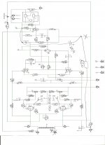
Anatoliy, your schematic is scaled down to small to read. Maybe I can download it or something.
Anyway, doesn't a concertina retain the SE distortion profile? There's not any f2 cancellation mechanism. And the circuit has such a musical name.
Cheers,
Michael
A resistive loaded concertina with followers doesn't have any feedback either. The followers need to be V/I converters (LTP idea...). After much tail chasing I put it away as not useful in the current context.
Anatoliy, your schematic is scaled down to small to read. Maybe I can download it or something.
Anyway, doesn't a concertina retain the SE distortion profile? There's not any f2 cancellation mechanism. And the circuit has such a musical name.
Cheers,
Michael
Unbypassed cathode resistor increases current linearity and plate resistance, decreases Gm, does nothing to externally reconnect Mu broken by the screen. Indeed, if any Mu still exists, actively fights against it having any influence.
Thanks for the reply, been thinking about it for a few days. How does an unbypassed cathode resistor increase plate resistance? I am thinking that plate current changes with plate voltage according to grid to cathode voltage, I think I am missing something fundamental to understanding this...
Another question, it seems there are advantages to using fixed bias, is the only disadvantage the fact that you have to come up with a neg bias voltage on the grid?
Thanks for any answers...
Unbypassed cathode resistor effectively reduces gm, but leaves mu unchanged. Anode resistance Ra=mu/gm, so as gm goes down Ra goes up.
Another way of looking at it is to realise the cathode resistor samples (and hence controls) the output current via negative feedback to the cathode. Just as sampling voltage NFB reduces output impedance, so sampling current NFB raises output impedance.
Another way is to do a thought experiment. Raise the anode voltage a little. This increases current and so increases the voltage drop across the cathode resistor. This reduces the valve current (raising the cathode voltage has the same effect as lowering the grid voltage), so offsetting the original change. Less current change for a given voltage change means higher impedance.
Fixed bias has the disadvantage that it can't automatically cope with valve ageing or mismatch.
96>Unbypassed cathode resistor effectively reduces gm, but leaves mu unchanged.
So are you saying, in concertina splitter for example: "effective" plate gain is still Mu?
Whichever (Mu or Gm) is the lesser gain, has the strongest control. Cathode resistor
may not directly "change" Mu, but decreasing Gm definately works against control by
Mu.
An unbypassed cathode resistor knows only current. It knows nothing of Voltage
seen at the plate. If our plate load is not entirely a linear resistance, we can only
guess the resistive part of that Voltage without controlling what really happens.
Wait, where was Mu? Sorry, we must have sabotaged it. Had no effect.
Strong control of current gives up control of Voltage.
Strong control of Voltage gives up control of current.
Can't have it both ways and still enforce linearity.
Last edited:
There are two (equivalent) ways to calculate the gain of a valve stage. One treats it as an imperfect voltage amplifier with an output impedance which is greater than zero. The other treats it as a transconductance amplifier with an output impedance which is less than infinite. Used correctly they both give the same answer. Some published formulas are approximations, so should only be used where the approximation is valid.
The first way you start from mu, then take account of the loading of the anode resistor and the following stage. The second way you start from gm x anode load, then take account of the shunting effect of the anode resistance.
If you add a cathode resistor, but have a perfect CCS anode load then you still get voltage gain of mu. A concertina splitter has a much lower load, so lower gain. The cathode resistor swamps gm so much that mu, although still present, has only a small effect.
Perfect control of current/voltage gives up control of voltage/current.
Partial control of one still grants partial control of the other - essentially you get perfect control of some linear combination of the two.
Schade IMHO: is the transformation of high impedance Pentode
curves to lower impedance Triode curves, by local nfeedback.
I believe that is the perfect definition.

Hi Michael;
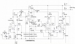
it is a thumbnail picture. Just click on it and get a big image that you can save.
A made a better drawing (attached)
Attachments
- Status
- This old topic is closed. If you want to reopen this topic, contact a moderator using the "Report Post" button.
- Home
- Amplifiers
- Tubes / Valves
- Topology for Schade