Economical volume pots that don't degrade the sound are hard to come by. I use the alps but still are 15 USD each with shipping.
I've just tried a simple voltage divider with a pot.
The input signal only goes through 1 resistor (I use a Allen Bradleyor Holco), and the bottom pot wired to earth is used to vary the voltage signal.
First impressions are very good. It's getting late, tomorrow I'll test more.
But this means I can use any old cheap pot to vary the voltage on the divider to adjust the volume as the signal only goes through the 1 good quality resistor.
Any drawbacks of this? Experiences?
get a second order function
Hi wavebourn.
not sure what you mean by this.
Do you have a diagram handy?
Any drawbacks of this? Experiences?
only drawback I can see is that it goes full volume input if you have an open section of track on your pot.
Possibly best used with speaker protection...
Hi wavebourn.
not sure what you mean by this.
Do you have a diagram handy?
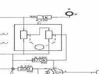
Like pictured.
The drawback is, on full volume it's input resistance is twice higher than on zero volume. But I used this feature for a ton-compensation, when used excess of power to extend bass. A cap before it was selected appropriately, and the amp had slight boost on bottom.
Attachments
Last edited:
Your cheap pot is shunting the signal. Thus it will have exactly the same effect as a normal pot arrangement. There is nothing magicly different about a component the signal goes "through" and a component the signal goes past. If it touches the signal, it affects it. Not everyone seems to realise this. You could argue that your arrangement is worse in this respect as the signal current is forced to go through the worst possible contact - wiper to track. A conventional volume pot feeding a high impedance stage simply picks off a voltage from a reliable potential divider - the wiper-track contact has to deteriorate quite badly before it affects the signal.
Your arrangement has the disadvantage that near maximum volume the output impedance remains high so it is less able to drive capacitive loads. Near minimum volume the input impedance reduces which could increase distortion in the previous stage. And when the slider lifts off the track?
Your arrangement has the disadvantage that near maximum volume the output impedance remains high so it is less able to drive capacitive loads. Near minimum volume the input impedance reduces which could increase distortion in the previous stage. And when the slider lifts off the track?
Why don't you find a couple of multi-position switches and make yourself a stepped attenuator
Tried this with a dual six pole switch from an old noise gate kit from Maplins, it was certainly a lot of effort getting the values of the middle switch settings to reflect my listening levels - and IIRC got quite complicated as each switch setting consisted of a sequence of resistors forming a potential divider adding up to 47k ( the value of the pot it was replacing ) I had access at the time to a large stock of resistors so was able to match the resistors closely. I measured my volume pot at my lowest and highest listening level and that defined the resistance range of the switch.
In the end I couldn't hear any difference between the pot and the switch, maybe when I get better speakers I will

p.s.
Now that I think about it my first experiment was to measure the resistance of my volume pot at my favourite listening level, then I replaced the pot with the equivalent circuit consisting of just two pairs of resistors. I dont recall hearing any improvement
Last edited:
Good comments and thanks for the drawbacks I was unaware of.
Certainly a couple of home made stepped attenuators could be attempted to avoid the drawbacks mentioned of the pot.
I used the alps as the bottom divider and certainly heard an improvement of the signal directly through the alps.
Certainly a couple of home made stepped attenuators could be attempted to avoid the drawbacks mentioned of the pot.
I used the alps as the bottom divider and certainly heard an improvement of the signal directly through the alps.
Pay particular attention to the second paragraph of DF96's post which implies that a shunt volume control should be loaded with a low capacitance stage-don't stick a D3A pentode triode wired after it!-and then you can use a higher value of series resistance so that the previous stage is not unfavourably loaded.Of course,if you do build a stepped attenuator you may have no reason to make it a shunt one unless you want to minimize the number of resistors/switch wafers and the number of solder joints in the signal path. Alex Djubuk in the Ukraine has fantastic switches at a good price.He is 100% reliable and 100% a gentleman.
I used the alps as the bottom divider and certainly heard an improvement of the signal directly through the alps.
A "standard" volume pot circuit and your "shunt" circuit provide different electrical conditions for the stages before and after the control. I'll believe that you heard a difference. If it was an improvement, it means that there's something less than optimal in the stage before and/or after the volume control. Perhaps you should look at those stages before blaming the pot.
Pay particular attention to the second paragraph of DF96's post which implies that a shunt volume control should be loaded with a low capacitance stage-don't stick a D3A pentode triode wired after it!-and then you can use a higher value of series resistance so that the previous stage is not unfavourably loaded.Of course,if you do build a stepped attenuator you may have no reason to make it a shunt one unless you want to minimize the number of resistors/switch wafers and the number of solder joints in the signal path. Alex Djubuk in the Ukraine has fantastic switches at a good price.He is 100% reliable and 100% a gentleman.
linky would be appreciated if you have it.
If it was an improvement, it means that there's something less than optimal in the stage before and/or after the volume control
I have an excellent SRPP headphone amp that sounds outstanding. Nothing less than optimal here. AB resistors, alps, 6N6P's, running at 18mA. Hexfreds, lytics bypassed with Russion PIO caps, DN2540 current sources on plates. Very nice set up.
Hello.
Try this.
NEW! The New-Old TCJ Stepped Attenuator
Works great.
DT
Thxs DT. Yes JB's work is good. But these work out more expensive than the good old alps.
I have an excellent SRPP headphone amp that sounds outstanding. Nothing less than optimal here. AB resistors, alps, 6N6P's, running at 18mA. Hexfreds, lytics bypassed with Russion PIO caps, DN2540 current sources on plates. Very nice set up.
Thxs DT. Yes JB's work is good. But these work out more expensive than the good old alps.
Hello Brit01,
DiyAudio.com makes the world small. You are 8 time zones ahead of me.
A bit tongue in cheek, with a rig like yours you need to try a Stepped Attenuator. They have perfect tracking even at full minimum setting. Before I included a buffer for a SET driver (too much gain) I found none of the dual log pots did a good job of tracking at the lowest level on the pot.
DT
All just for fun!
Your cheap pot is shunting the signal. Thus it will have exactly the same effect as a normal pot arrangement. There is nothing magicly different about a component the signal goes "through" and a component the signal goes past. If it touches the signal, it affects it. Not everyone seems to realise this.
Least of all those who came up with the "shunt" idea in the first place.
They say that the pot "isn't in the signal path" when in fact the voltage across the pot IS the signal; a consequence of the current flowing through it.
se
Perhaps you should look at those stages before blaming the pot.
I agree
Brit01 said:Nothing less than optimal here. AB resistors, alps, 6N6P's, running at 18mA. Hexfreds, lytics bypassed with Russion PIO caps, DN2540 current sources on plates.
That you have "AB" resistors (whatever that is), "hexfreds" and "pio caps" changes nothing to the fact that the stage may react differently to the different load/source impedances presented by the two pot arrangements. It might even sound better because there is higher distortion now
How an audio stage behaves is 98% due to topology and component values and only 2% due to choice of components.
[snip]But this means I can use any old cheap pot to vary the voltage on the divider to adjust the volume as the signal only goes through the 1 good quality resistor.
Any drawbacks of this? Experiences?
The drawback is in the assumption that the pot isn't in the signal's way with this shunt. It is; all the reasons you would have for or against a pot are equally or more valid in the shunt arrangement.
In fact, you're going backwards; instead of the wiper feeding a high input impedance of the next stage, which asks almost no current, now the wiper carries the signal current to ground which generally is much larger, so the wiper/pot gets even more critical.
jan didden
Pay particular attention to the second paragraph of DF96's post which implies that a shunt volume control should be loaded with a low capacitance stage-don't stick a D3A pentode triode wired after it!-and then you can use a higher value of series resistance so that the previous stage is not unfavourably loaded.Of course,if you do build a stepped attenuator you may have no reason to make it a shunt one unless you want to minimize the number of resistors/switch wafers and the number of solder joints in the signal path. Alex Djubuk in the Ukraine has fantastic switches at a good price.He is 100% reliable and 100% a gentleman.
did someone call me?
Mike,linky would be appreciated if you have it.
from memory his ebay user name is alex_550. I will check this when I finish work.
- Status
- This old topic is closed. If you want to reopen this topic, contact a moderator using the "Report Post" button.
- Home
- Amplifiers
- Tubes / Valves
- Voltage divider instead of expensive volume pot or stepped attenuator.