I will mock it up electrically prior to drilling any holes and mounting it permanently as there are other ways to address this issue.
Like this?
Attachments
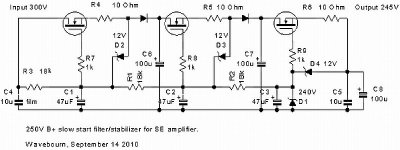
Some notes on construction:
The chassis is effectively grounded right at the point where the power cord plugs in.
The amplifier signal and power grounds run to a common ground bus, and from the ground bus there is a single 10 ohm resistor and pair of anti-parallel diodes (3A recommended) to the chassis ground.
There are no hum issues or ground loop problems.
The chassis must be metal over the majority of its area and have a metal bottom cover. The impedances are quite high in this design, and the bandwidth is not as limited as you would think. It will oscillate without careful layout as I discovered despite reasonable efforts in this direction.
There are several chassis makers now selling on eBay that make very nice and reasonably priced solid, strong aluminum chassis with wood end caps. I recommend them. (Mine came from eBay)
Unlike me I do recommend placing the RCA jacks near the 6J7 not 20cm away as I did. Shielded wire from the grid cap is de rigeur, and I strongly recommend placing the grid stopper right at the cap. Feedback connections must not leave the vicinity of the 6J7 - install both feedback resistors right at the socket and carefully run the primary and secondary feedback lines from the transformer to the respective resistor. Use a low inductance film cap on the screen grid. Keep leads short and dress near chassis for shielding.
Screen and grid stopper resistor on the 6V6 should be mounted snug to the socket.
You may not see the RF on your scope but it will be there if as I learned with the slightest provocation.
Choose a transformer with good HF behavior and sufficient inductance for good LF performance.
If you use electrolytic caps in the supply as I had to due to space constraints it is a good idea to shunt them with 0.47uF - 1uF caps.
This should be a good project for someone looking for a small, efficient amp for efficient speakers.
Interesting thread, interesting catch of the problem.
Out of curiosity why the fixed bias? What's the advantage?
(I've been eyeballing the 12V garage door remote batteries in the kitchen drawer)
It's one of my long standing design trade marks and eliminates what is usually a really bad capacitor directly in the signal path. Large film caps while better than electrolytics are not as transparent as a small resistor or piece of wire - at least at any price point I can (un)reasonably afford. In more sophisticated designs than this the use of fixed bias and a bias adjustment pot allows one to choose any OP compromise one desires based on load characteristics, life vs performance trade offs, varying tube characteristics by brand/version, and "tuning/tweaking." In higher power designs using tubes with significant bias voltage requirements (like 300B/GM70/211/845 or even the mundane 6550/KT88) it is also significantly more efficient electrically and thermally speaking.
Nice one, Kevin! I wonder how well some of the TV vertical deflection 6V6 variants like 6JB5, 6JC5, 6HE5, 6EY6 or 6EZ5 would work. Then there is the 6MF8 which is basically a 6EZ5 and 12AT7 sharing a compactron bulb - these also make nice voltage regulators, by the way. These alternate tubes heve nearly identical operating characteristics as 6V6, with possibly the exception of the grid biasing voltage (generally stated as being around -20 to-22V.
I haven't tried 6J7s or 6SJ7s yet as drivers, though I do have a goodly supply of there. I guess I'm too much ingrained into using triodes as drivers.
In guitar amp service, 6V6GTs can really take a "whipping" - the Fender Deluxe clone that I just completed runs the B+ around 370VDC,and the cathode current around 86 to90 mA for the PP pair, depending on the brand of 6V6s that I run in it. Cathode resistor is 250 ohms, 5W, shared. So in this case the cathodes are approx 22VDC higher than the grid voltage (just like 6JB5s?) . So we're talking about 350VDC V P-K at 45 mA being dissipated in these tubes. The screengrid current is a few mA, but still, the plate dissipation goes well beyond 15W.
I really like the sound of the vintage oval plate 6V6GTs, but the new J/J 6V6S are amazing, their internal structure looks more like that of a downsized 6L6GC, and the definitely are very tough tubes. Interestingly, the matched pair I have, is very well electrically matched, but the glass bulb is about 1/4 inch taller in one than the other.
The innards appear identical, and sit at the same level in regards to the tube's base.
/ed B in NC
6П6С is a fair 6V6 copy, but has wide spread of parameters like all Russian tubes.
Isn't the 6П1П also a close (but smaller) one? Just like the 6AQ5 used to be to the 6V6GT...
OH, yeah while I was at it I dropped in a pair of $1 tubes. The current went up to 57 mA (expected) and the sound got fatter with more bass. Maybe I will just turn the power supply up a bit.......Nice one, Kevin! I wonder how well some of the TV vertical deflection 6V6 variants like 6JB5, 6JC5, 6HE5, 6EY6 or 6EZ5 would work.
The $1 tube was a 6EZ5. I have stuffed them into a few 6V6 amps. They will draw a bit more current, so it may not be a good idea if the amp is already near meltdown, but they do sound nice.
The supply in this amp is happy providing 100mA or so, but not a whole lot more than that - so I am stuck with 6V6..
I did add a switch for triode/pentode mode, power output capability drops drastically, and the power supply buzz is at least 6dB worse due to a lack of open loop gain.. Hard to judge whether or not triode sounded better for both reasons. (Should be easier to tell once the supply choke is installed.)
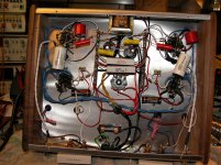
The OPTs are very small, occupying about half the internal volume of the covers. My suspicion is that they would perform much better driven by the relatively low rp of a 45, 6CK4, or 6AH4. I'm thinking that a pair of Edcore transformers might be in the not too distant future, better if they fit under the current covers.
I've attached a look under the hood. Please bear in mind I built this thing in about 8hrs total..
I did add a switch for triode/pentode mode, power output capability drops drastically, and the power supply buzz is at least 6dB worse due to a lack of open loop gain.. Hard to judge whether or not triode sounded better for both reasons. (Should be easier to tell once the supply choke is installed.)
The OPTs are very small, occupying about half the internal volume of the covers. My suspicion is that they would perform much better driven by the relatively low rp of a 45, 6CK4, or 6AH4. I'm thinking that a pair of Edcore transformers might be in the not too distant future, better if they fit under the current covers.
I've attached a look under the hood. Please bear in mind I built this thing in about 8hrs total..
Attachments
Last edited:
Well, let's check the practical issues learned while building
this amp
grid stoppers everywhere
g1 grid stopper right at the grid cap
shielded grid cap wire, rca sockets as near as possible to the
driver tubes
components soldered right at the socket pins, as extensively as
possible
shielded NFB wires
very judicious cable lay out
fully metal chassis (i like this part)
PSU tube rectified, CLCLC filtered , and lytics filter caps
preferably bypassed by small film caps
TU`s with generous primary inductance, preferable
If one really want to reach 5W output, most probably will need to
abuse the plates say B+300 or more, while keeping the grids at
the rated 250V
forget something?
Think you got pretty much all of it, including the need to abuse the 6V6 seriously in order to get anything approaching "Power" said in the best Jeremy Clarkson-esque manner.. (Top Gear reference )
I only used electrolytics in the PSU because I did not really have the space for film types which I personally prefer..
You might get away with a little more voltage on the screens, but I'd probably not let it go over 275V..
Primary inductance is very important..
Triode connection option on the 6V6s is not recommended unless you disconnect the secondary feedback as well, are prepared to possibly tinker with the internal feedback loop, and need only a miniscule amount of power. It might sound better, but I can't tell yet. (Need that choke!!!!)
)I only used electrolytics in the PSU because I did not really have the space for film types which I personally prefer..
You might get away with a little more voltage on the screens, but I'd probably not let it go over 275V..
Primary inductance is very important..
Triode connection option on the 6V6s is not recommended unless you disconnect the secondary feedback as well, are prepared to possibly tinker with the internal feedback loop, and need only a miniscule amount of power. It might sound better, but I can't tell yet. (Need that choke!!!!)
Last edited:
Triode connection option on the 6V6s is not recommended unless you disconnect the secondary feedback as well, are prepared to possibly tinker with the internal feedback loop, and need only a miniscule amount of power. It might sound better, but I can't tell yet. (Need that choke!!!!)
For triode connection, still keeping it simple, you would better go for 275-280V anode supply at -19 to -20V (for about 40 mA) and 5K load. You should get more than 1.6W just like a "conventional" 45 SE run at 250V. In this case it isn't that different in terms of plate resistance too. So any good OPT for a 45 will do. Still less efficient in terms of Pout/Pdiss, but at least this is much easier to drive in terms of driving voltage and you could make some sort of comparison.
Among electrolytics try some good axial types: lower losses and overall better performance.
Cheers,
45
....in order to get anything approaching "Power" said in the best Jeremy Clarkson-esque manner.. (Top Gear reference
There some good stuff in here!!
YouTube - Top Gear reviews the Ferrari 458 Italia
For triode connection, still keeping it simple, you would better go for 275-280V anode supply at -19 to -20V (for about 40 mA) and 5K load. You should get more than 1.6W just like a "conventional" 45 SE run at 250V. In this case it isn't that different in terms of plate resistance too. So any good OPT for a 45 will do. Still less efficient in terms of Pout/Pdiss, but at least this is much easier to drive in terms of driving voltage and you could make some sort of comparison.
Among electrolytics try some good axial types: lower losses and overall better performance.
Cheers,
45
All good tips, and pretty much consistent with what I would do, and might still do.
I actually started with all axial supply caps, but needed much more capacitance to tame the PSU supply ripple issues. The performance of those radial caps vis a vis ESR etc is quite good. They're a premium HV Panasonic that I have used in other applications without issue. Axials do not represent good volumetric efficiency and since space is getting very limited I might unfortunately have to stick with these. (I'll prospect thought, who knows what I'll find.)
The input cap is currently an FT 10uF axial which I will replace with a 33uF FT axial tonight when I install the new supply choke. I am going to use a GZ32 rectifier going forward so this should get me around 280V of DC, I may drop the screen voltage slightly if it seems excessive, but there is no supply margin left current-wise with the boosted plate current for actual screen regulation. The PC8404 is very conservatively rated at 90mA DC and I am only using half of the available 6.3V filament power rating which keeps the transformer core operating at under 60 degrees C after several hours of use, but I shouldn't push it any further IMHO so regulated screens appear to be out of the question. Load current as it stands is around 108mA, and I knew it would be marginal going in - I needed a very compact transformer and had originally planned to limit current to <95mA total, but excessive heating has not been a problem. This transformer is virtually silent under load, back in the 1950s these guys knew exactly what they were doing. Stancor PTs IMHO are great in every experience I have ever had with them. (Strangely enough these days my line voltage is almost always within a volt of 117V at any time of the day - it used to be much higher, and that probably helps.)
Given the current OPTs and their inadequate to the task primary inductance I will probably end up replacing them with Edcors sometime next month. Sadly in every other way they are completely beyond reproach and probably would work excellently with a pair of 45s with their comparatively low rp.
Retaining triode mode is not a given either, I will need to evaluate what it brings to the table once the supply issues are fully addressed. It seems that the design in many respects is not optimal for triode connection.
Last edited:
At the risk of sounding totally silly I think Top Gear is flat out the best automotive TV show I have ever seen. I watch it religiously every week on the BBCA..("The beeb")
Instead of triode connection I would suggest you to try to power screens from an active filter consisting of high resistance voltage divider shunted by a big enough capacitor and a source follower. I.e. low dynamic resistance, and very low ripples.
I might be able to fit that in somehow.. Need to get some more HV mosfets first though.
- Status
- This old topic is closed. If you want to reopen this topic, contact a moderator using the "Report Post" button.
- Home
- Amplifiers
- Tubes / Valves
- 6V6 Behavior W/Fixed Bias (SE Amp)