Tube tester has a "short" test which is the first test you should (always) perform!
I just got an Arduino Leonardo which is going to form the basis of a new, open source, tube and transistor tester.
Please tell us more, is it similar to Michael Koster's concept?
Jaz
Thanks Alfredo, will look at this!
A quick example for 4P1L curves. Quite interesting tool indeed
http://www.bartola.co.uk/valves/wp-content/uploads/2012/09/4P1L-curves.png
Ale
Please tell us more, is it similar to Michael Koster's concept?
Jaz
No, not really. I have no issues with transformers.
The Leonardo behaves as if it were a USB device, i.e. no FTDI chip.
I published a tracer article about 10 years ago using the Basic Stamp -- it worked but was slow due to communication speeds. I've gotten a lot better at current sensing, stabilising power supplies etc.
The important thing for me is to be able to dump the data into Eurequa to come up with equations.
How difficult is to work with Eureqa to produce the triode model?
I've been using Dmitry's paint tools with good results except for power transmitting DHTs..
It's pretty straight forward with Eureqa, it take about 10-20 minutes to generate an usable solution. I never got the hang of using Model Curve Painter, the curves never lined up for me...
 So for triodes, my favorite is still Curve Captor - it's quick, accurate and does loadlines, Pd and THD calculations on-the-fly.
Jaz
Tube tester has a "short" test which is the first test you should (always) perform!
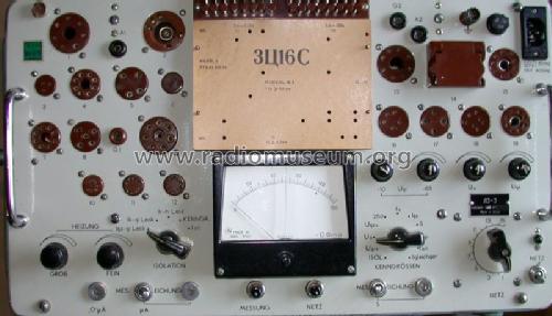
That's a good point... Besides having all the tube sockets pre-wired (a real time-saver), the tube tester also have select-able voltages for the plate and screen (although only up to 300V). Here is the tester I plan on using, if anyone has other suggestions, please let me know.

which is a copy of this Russian unit.
Thanks,
Jaz
Ale, great job! See you have been busy tracing.
I built a camera hood that works great for me. It is made of 1/4 inch hard foam that is used for posters. The hood is light and strong and snaps tightly against the oscilloscope screen frame.
What settings are you using on the camera? I think you mentioned that you have a storage scope as well, right? BTW, thanks for posting the as-built schematic.
Jaz
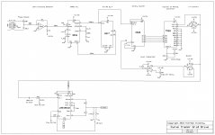
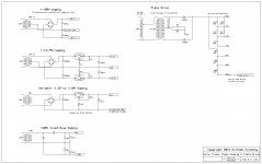
After a lot of work (more than I thought it was going to take), managed to bring the valve curve tracer to life.
Cheers,
Ale
Ale,
Sorry to bother you again... What are the front panel controls highlighted in the attached picture? I can't see them on your schematic.
Thanks,
Jaz
An externally hosted image should be here but it was not working when we last tested it.
Ale,
Sorry to bother you again... What are the front panel controls highlighted in the attached picture? I can't see them on your schematic.
Thanks,
Jaz
An externally hosted image should be here but it was not working when we last tested it.
Hey Jazz,
I'm on the road with no laptop.
Ia: is the pot for the dn2540 cascoded CCS I use for measuring transconductance and THD
G: grid output to calibrate steps using the scope
Grid zero: bias pot to set Grid starting point of Vgk curves
Switch on the bottom is power switch
Ia switch disconnects HT from CCS
All that part of the circuitry blew up with my last 600V test. Hopefully I will sit down to repair it when back
Cheers
Ale
Ale: You've done such nice work on the instrument, why not get a silk-screen kit for the lettering.
You may be right, but haven't done that before, any idea what/where to get it from?
Thanks!
All that part of the circuitry blew up with my last 600V test. Hopefully I will sit down to repair it when back
Cheers
Ale
Thanks for the clarification.
Too bad about your gm/THD test rig, I read about it on your blog, something to do with Millet's soundcard input, was it? I am still gathering parts for the build and going over the Tek 570 schematic, I'd love to incorporate the Plate-Screen-Grid switch for the vertical amp, but the switching and the extra power supplies are not "DIY friendly"... Those Tek engineers sure knew what they were doing!Thanks,
Jaz
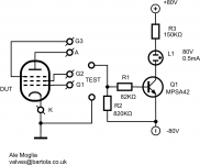
Leakage testing circuit
Thought about the addition of a simple short/leakage testing to my tester. Now that will have to open and do some repairs, I can easily drill a couple of testing connectors and use existing +/- 80V supply available.
I thought about the proposed leakage circuit in the Sussex tester, so came up with the simple modification in the attached.
With a couple of probes can use this to test anode/grid leakage, filament continuity and cathode leakage as well.
Only concern is whether gain is too much. MPSA42 has an hFE=90@Ic=1mA. So input sensitivity is about 5uA to light the russian neon bulb.
Looked around for grid current values thresholds used in testers but couldn't find any. Old testers use a simple neon bulb to identify leakage so I guess they are measuring 100uA or above in order to get a dim light on the neon bulb?
Suggestions?
Thanks
Ale
Attachments
see the Neuberger tube manual . http://www.jogis-roehrenbude.de/Roehren-Geschichtliches/Roe-Pruefer/Neuberger-400/RMP400.pdf
There is a part about grid current See Page 18b
"the value of the measured grid current can be used as a criteria, as a rule of thumb
Tubes whit a Bad vacuum (tested bad on the procedure in 18A)
preamp tubes whit less than 4 uA are usable
output tubes whit less than 10 uA are usable
tubes that are good and show little Gas on the gas test.
should have less than 0,6-1uA for preamp tubes and less than 1.5-2 for output tubes.
lot of useful data in that manual.
v4lve
Thanks v4lve!
So in principle 5uA is not bad at all for this purpose. This circuit should work fine. Can build it very quickly and report results.
Only point is that output valves with 5-10uA will turn on the lamp
I'm trying to avoid the addition of a grid sensing resistor and an op amp and the output to measure the grid current externally, no additional space inside the tracer am afraid.
Ale
see the Neuberger tube manual . http://www.jogis-roehrenbude.de/Roehren-Geschichtliches/Roe-Pruefer/Neuberger-400/RMP400.pdf
lot of useful data in that manual.
v4lve
Wish I could translate this, but unfortunately don't speak German!
I'm also thinking about incorporating a shorts test into the tracer, I like the B&K version, the detailed schematic is in the B&K 747 tester if you want to take a closer look, the basic setup is as follow:
Jaz
An externally hosted image should be here but it was not working when we last tested it.
Jaz
How to get rid of re-trace?
I ran a quick test on my adapter this morning, it worked BUT how do I get rid of the re-traces from the display? I played with the Phase and Sweep adjustments (per Ale's schematic), but they did not seem to have an effect... I also tried blanking the Z-axis by connecting the Y-sweep to it, which helped may be a little, but most of the re-traces remained... Did I overlook something obvious?
Jumbled curves:
TIA,
Jaz
I ran a quick test on my adapter this morning, it worked BUT how do I get rid of the re-traces from the display? I played with the Phase and Sweep adjustments (per Ale's schematic), but they did not seem to have an effect... I also tried blanking the Z-axis by connecting the Y-sweep to it, which helped may be a little, but most of the re-traces remained... Did I overlook something obvious?
Jumbled curves:
An externally hosted image should be here but it was not working when we last tested it.
TIA,
Jaz
Last edited:
- Status
- This old topic is closed. If you want to reopen this topic, contact a moderator using the "Report Post" button.
- Home
- Design & Build
- Equipment & Tools
- DIY Curve Tracer